

Galvanized metal objects and their manufacturing process
a technology of galvanized metal and manufacturing process, which is applied in the field of galvanized metal manufacturing, can solve the problems of limiting the competitiveness or the type of products that can be assembled, the method is not applicable in practice, and the significant health hazards of the welding process are the generation of fumes and gasses, and achieves the effect of efficient production
Active Publication Date: 2015-09-10
FONTAINE HLDG NV
View PDF11 Cites 0 Cited by
- Summary
- Abstract
- Description
- Claims
- Application Information
AI Technical Summary
Benefits of technology
The present invention is about a new method for producing high-quality corrosion-resistant three-dimensional objects made of metal, such as steel, without the need for metal galvanization after forming. The method involves pre-cutting metal sheets with multiple free edges and is applicable to various cold forming methods. It ensures full coverage of the metal surface, providing protection against corrosion and other environmental factors, and is cost-effective compared to prior art techniques. The invention also involves a process called punching, which uses a press to create holes in metal sheets.
Problems solved by technology
However in the case of galvanized steel sheets, some of these methods are not applicable in practice or suffer strong constraints that limit their competitiveness or the type of products that can be assembled.
For instance, one of the most significant health hazards of the welding process is the generation of fumes and gasses.
Without proper personal protection, one or two hours after welding one may experience severe symptoms such as thirst, pain in the legs, congestion in the head, throat dryness, and cough.
However the above quoted prior art references do not address the issue of making certain types of galvanized three-dimensional metal objects of complex shape.
In particular they do not address the difficulty of dealing with a galvanized metal, especially galvanized steel, cut thin sheet matrix with a shape including multiple free edges.
In this circumstance, in addition to the avoidance of cracks in the thin galvanizing coating, the ductility of an aluminium-containing galvanizing coating in combination with the requirement of fastening the multiple free edges represents a challenge to form the final object.
This is presumably due to the lack of suitable and non-expensive manufacturing process, as outlined above.
As a result of their relatively high production costs such galvanized steel boxes or enclosures have found limited uses in the electrical industry, for instance as junction boxes (for encasing shunts) including galvanized steel solid sheets 1.52 mm thick, with a very small vent area provided on their front door to keep dust-proof and waterproof, and usually also including a galvanized steel continuous hinge and a hasp for padlocking.
The currently available manufacturing processes for producing galvanized steel three-dimensional objects of any complex shape and size suffer from many restrictions and therefore cannot properly fulfill the main market requirements.
However one first disadvantage of the currently known procedure is that cutting of the metal sheet matrix is carried out after the galvanizing step, and hence the cutting edges are free from the zinc-based galvanizing coating and therefore left without protection against corrosion.
This is in most circumstances not acceptable.
A post-galvanization cold forming of a metal sheet matrix is usually not satisfactory with a hot dip galvanization method using a standard pure zinc bath since the resulting zinc-iron coating layers are brittle and the metal sheet forming process will inevitably lead to cracks in the protective coating and therefore to a significant reduction of the protection of the three-dimensional object against corrosion, not only instantly but also in the long term.
A disadvantage of a currently known procedure wherein galvanization is performed after forming the object is that transporting the three-dimensional object from the forming section of the plant to the galvanizing section involves a lot more space in the production plant than actually necessary, therefore additional costs especially if the object has a substantial volume.
Method used
View moreImage
Smart ImageViewing Examples

Examples
example
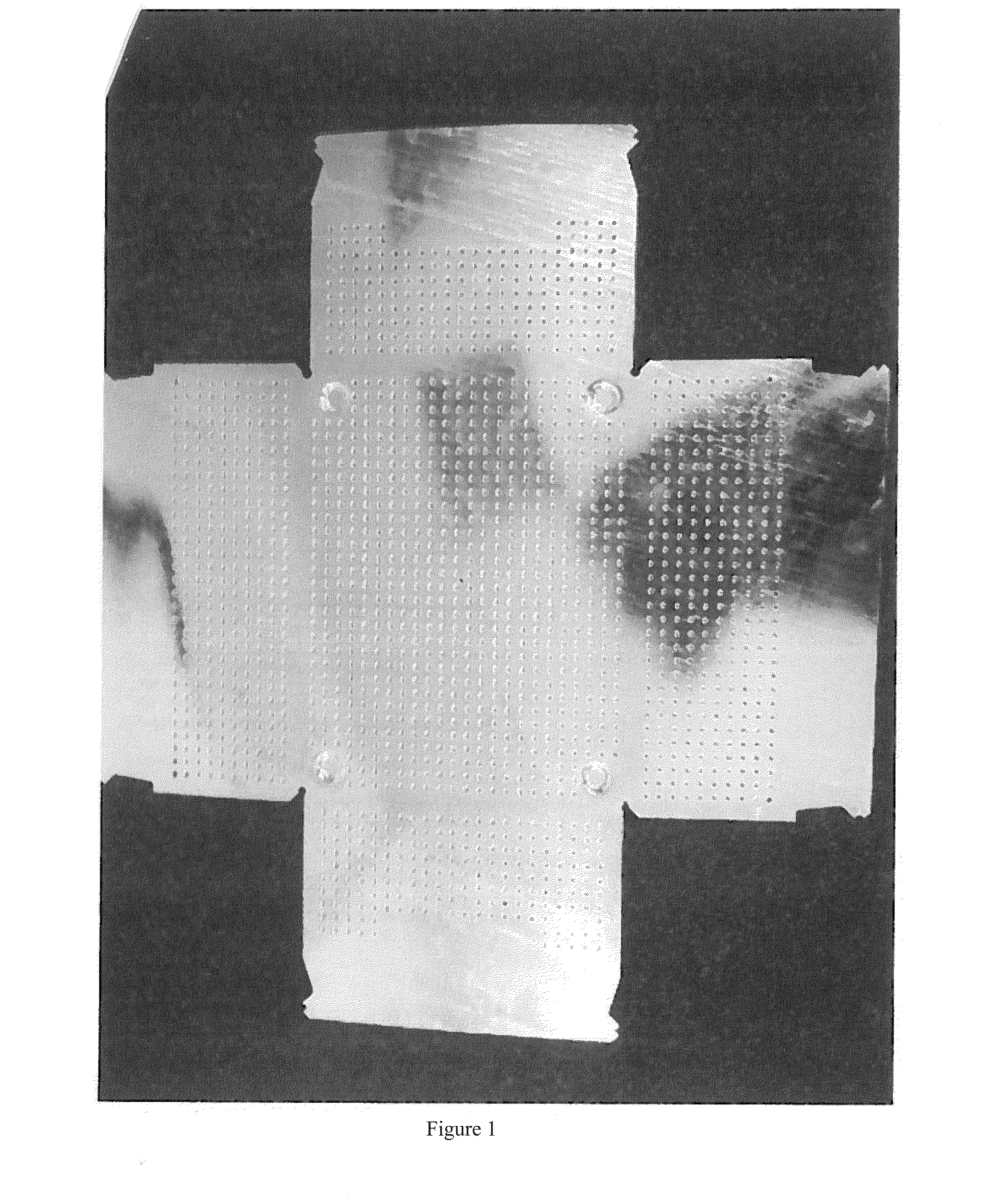
[0043]A parallepipedic box with dimensions 40 cm×30 cm has been produced from the pre-cut steel sheet matrix with multiple free edges and with punched holes shown in FIG. 1, the said sheet matrix having a thickness of 1 mm and being coated with a 10 μm thick zinc alloy layer obtained by hot dipping into a molten bath of a zinc alloy comprising 5% by weight aluminum, followed by bending the wall portions at perpendicular angle with respect to the central portion to form the desired parallepipedic shape, and finally forming a series of clinching pints for fastening the multiple adjacent edges. The resulting box is highly corrosion resistant and may be useful, inter alia, for transporting goods.
Login to View More PUM
| Property | Measurement | Unit |
|---|---|---|
| thickness | aaaaa | aaaaa |
| thickness | aaaaa | aaaaa |
| temperature | aaaaa | aaaaa |
Abstract
This invention provides process for manufacturing a galvanized metal three-dimensional object with a shape including multiple edges, said process comprising, in the following order, the steps of:(A) providing and cutting a metal sheet matrix with a thickness within a range from 0.8 mm to 6 mm, the shape of said metal sheet matrix including multiple free edges,(B) batch-wise hot dipping said metal sheet matrix into a molten zinc alloy galvanizing bath,(C) cold-forming the galvanized metal sheet matrix into a desired three-dimensional shape including multiple adjacent metal edges, and(D) cold-forming a series of joining points for fastening together said multiple adjacent metal edges, to form said galvanized metal three-dimensional object.
Description
FIELD OF THE INVENTION[0001]The present invention relates to the manufacture of galvanized metal, especially galvanized steel, objects with a complex shape. In particular the present invention relates to the manufacture of galvanized metal, especially galvanized steel, objects with a shape including multiple edges wherein manufacturing requires forming such objects from a thin metal sheet matrix including multiple free edges and galvanizing said metal sheet matrix. The present invention also relates to such galvanized metal, especially galvanized steel, objects with a complex shape as far as they cannot be produced by means of the currently available manufacturing processes.BACKGROUND OF THE INVENTION[0002]It is generally known that metal sheets can be assembled by means of welding, riveting, clinching, gluing, crimping, screwing or clip fixing. However in the case of galvanized steel sheets, some of these methods are not applicable in practice or suffer strong constraints that limi...
Claims
Login to View More Application Information
Patent Timeline
 Patent Type & AuthorityApplications(United States)
IPC IPC(8): B21D39/02C23C2/06B32B15/01C23C2/34B21D5/16C23C2/02C23C2/26
CPCB21D39/026C23C2/02C23C2/06B32B15/013C23C2/34B21D5/16C23C2/26B21D39/03B21D51/52C21D7/02C23C2/30F16B5/045F16B5/07B65D1/22C23C2/405Y10T428/12361Y10T428/12799C23C2/024C23C2/022
InventorBAUMGURTEL, LARSRAHLKE, MICHAEL
OwnerFONTAINE HLDG NV