Bottomless-cup type water power conversion device utilizing flowing water energy

a water power conversion device and bottomless cup technology, applied in the direction of marine propulsion, machines/engines, vessel construction, etc., can solve the problems of limited maximum power generation volume of one wind power generator, inability to use drag-type waterwheels in patent literature 1, and inability to achieve drag-type waterwheels. , to achieve the effect of reducing the cost of operation

Inactive Publication Date: 2015-09-10
TADAO SHIMIZU
View PDF20 Cites 7 Cited by
  • Summary
  • Abstract
  • Description
  • Claims
  • Application Information

AI Technical Summary

Benefits of technology

[0139]The drag-type water power conversion device for converting flowing water energy to rotational force pertaining to the present invention has a simple structure and can efficiently convert the energy of flowing water to rotational force.
[0140]Handling changes in ocean current is also easy, and high-capacity power generation is possible with a small device.
[0141]The initial investment is small and the running cost is also low. Furthermore, the device demonstrates excellent durability.

Problems solved by technology

As for drag-type waterwheels, none of the methods to allow these waterwheels to be used underwater as presented in Non-patent Literature 1 have been commercialized, and drag-type waterwheels presented in Patent Literature 1 are not feasible due to concerns over large losses occurring at the drawing port.
Accordingly, the problems can be explained as follows using general-purpose wind power generators as representative examples: lift-type wind power generation is a method to obtain and utilize the maximum kinetic energy, but the maximum power generation volume of one wind power generator is limited partly because excess energy can be controlled only by means of cutoff, and partly because the adaptive flow velocity range is narrow due to stalling.
Furthermore, because the plane of rotation forms a single disk, high-speed rotation creates disturbance that in turn prevents the blade effect from being achieved, and therefore the blade width and number of blades are kept small as described in Non-patent Literature 2; however, this leads to a contradictory result of increasing the dead flow volume that flows through gaps between the blades and thus exerts no power at all and the efficiency falls between 30 and 40%, while generating motive power of large power and small torque is not suitable for generators that require large torque.
Moreover, generators positioned side by side cannot be connected together, which makes it impossible to achieve high-capacity power generation, and a forest of many generators cannot reduce the cost.

Method used


Image

  • Bottomless-cup type water power conversion device utilizing flowing water energy
  • Bottomless-cup type water power conversion device utilizing flowing water energy
  • Bottomless-cup type water power conversion device utilizing flowing water energy

Examples


Embodiment Construction

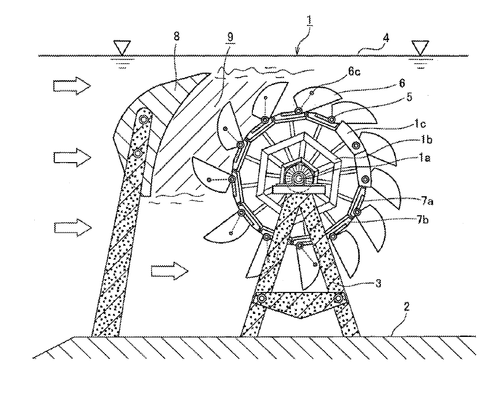
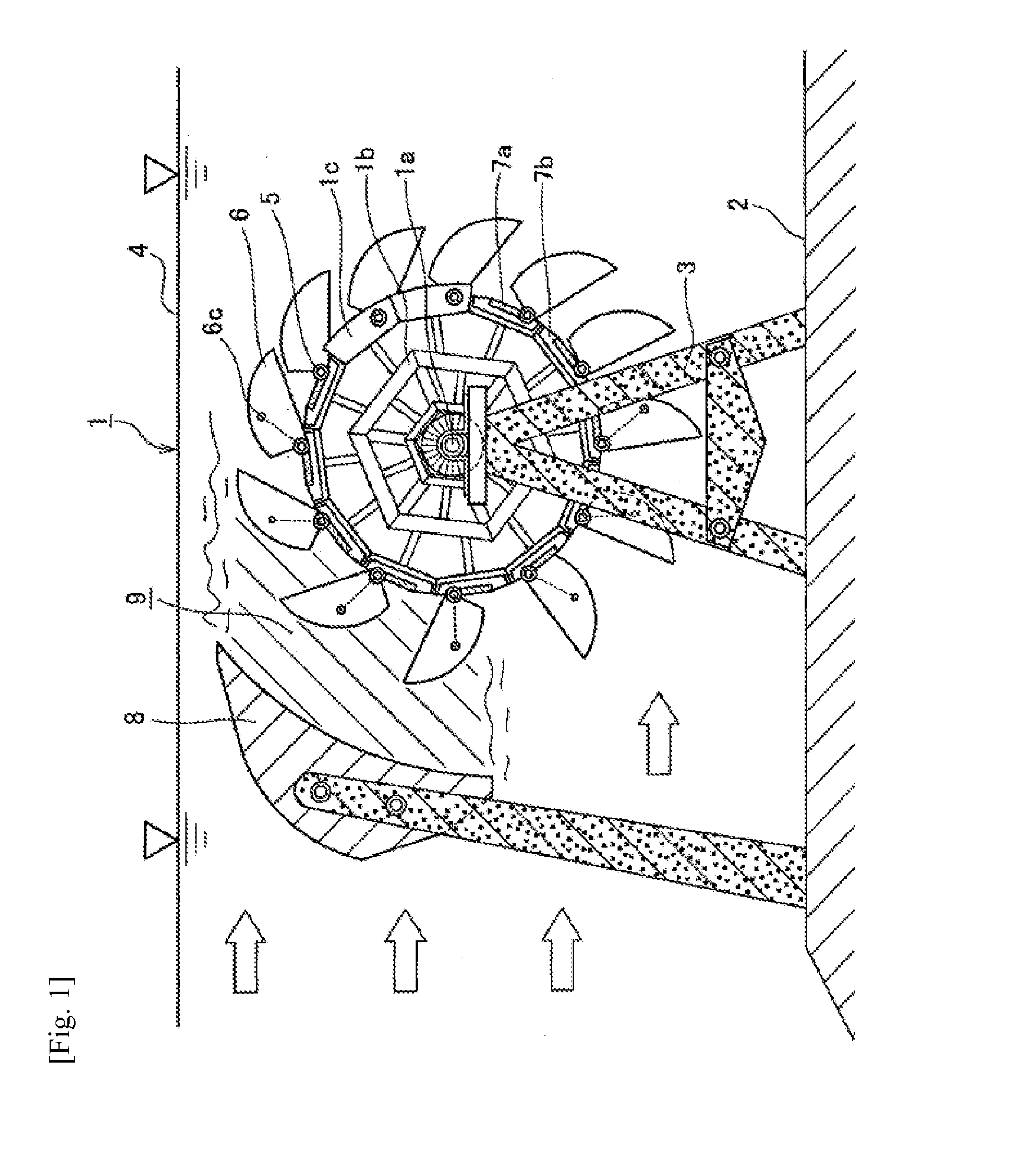
[0177]A water power conversion device of uniaxial waterwheel type pertaining to the present invention is shown in FIG. 1.

[0178]Since an underwater waterwheel 1 is of drag type, a rotational shaft 1a is placed at right angles to flowing water in order to simultaneously create a forward advance path for turning in the same direction as flowing water and a reverse advance path for turning in the opposite direction, where the waterwheel turns as a result of the drag difference between the two.

[0179]In the example in FIG. 1, the underwater waterwheel 1 is installed below a water surface 4.

[0180]A support column 3 is erected on a bottom face 2 and the underwater waterwheel is installed thereon.

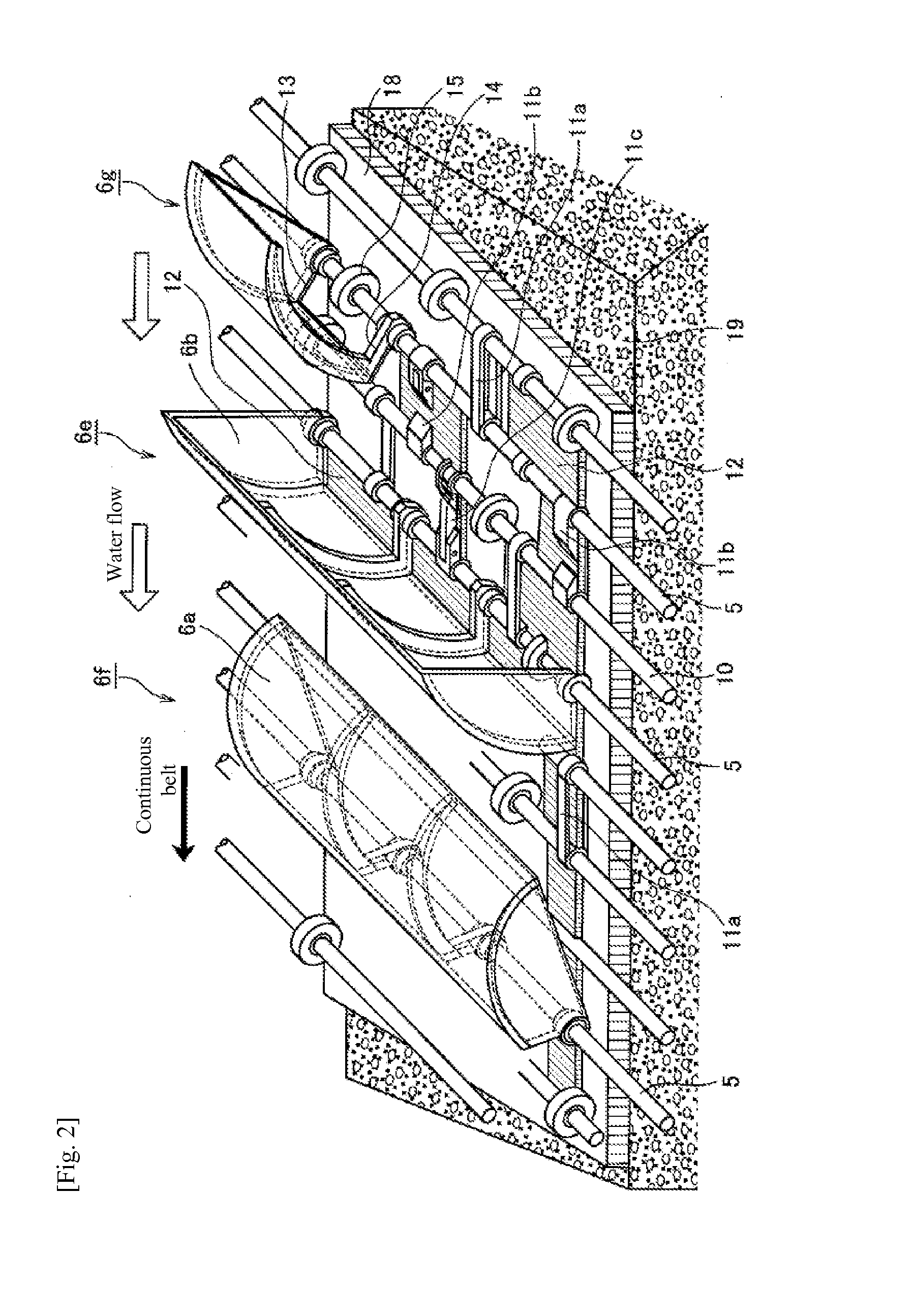
[0181]The water-receiving cup provided on an outer wheel 1c of the underwater waterwheel 1 is divided on one hand into a bottomless cup 6 integrally formed by a pressure-receiving plate 6a that receives flowing water and by a side plate 6b on both sides, and into a bottom plate 7 (7a, 7b) on the oth...


PUM


Abstract

A water power conversion device formed as an underwater waterwheel, includes: a cup constituted by a bottomless cup and a bottom plate, with the two parts fitted pivotally in a freely rotatable manner; a mechanism provided to cause the bottomless cup to block flowing water in a standing state, and to cause the bottomless cup to make flowing water pass through and around it in a lying down state, in order to generate flowing water resistance difference between the two states, wherein multiple units of this mechanism are installed on a continuous member, the cup stands in a forward advance path and lies down in a reverse advance path, and the bottomless cup is turned by centrifugal force from the lying down state to the standing state, and a water blocking plate is provided to make the cup turn or circulate continuously in water.

Description

TECHNICAL FIELD[0001]The present invention relates to a water power conversion device that converts the energy of flowing water to rotational force, and more specifically to a drag-type underwater waterwheel and underwater endless chain waterwheel.BACKGROUND ART[0002]Various methods to generate power using oceanic energy have been presented, but as far as the method to convert the water power of flowing water, which is the basics of oceanic energy, is concerned, lift-type vane wheels are still in the testing stage at the moment.[0003]As for drag-type waterwheels, none of the methods to allow these waterwheels to be used underwater as presented in Non-patent Literature 1 have been commercialized, and drag-type waterwheels presented in Patent Literature 1 are not feasible due to concerns over large losses occurring at the drawing port.[0004]In other words, while the methods to utilize the kinetic energy of fluid are largely classified into the lift type and drag type, the lift type is...

Claims


Application Information

Patent Timeline
Patent Type & Authority Applications(United States)
IPC IPC(8): F03B7/00
CPCF03B7/006F03B7/003F03B17/065F03B17/066F05B2240/121F05B2240/97Y02E10/30Y02E10/20
Inventor SHIMIZU, TADAO
Owner TADAO SHIMIZU
Why Eureka
Try Eureka