Multitone Harmonic Radar and Method of Use

a multi-harmonic radar and harmonic technology, applied in the field of multi-harmonic radar and method of use, can solve the problems of difficult to distinguish background clutter from background clutter using traditional linear radar, and the threat of rf electronics by warfighters, so as to reduce error, increase detection capability, and maximize efficiency

Active Publication Date: 2015-09-10
US SEC THE ARMY THE
View PDF2 Cites 11 Cited by
  • Summary
  • Abstract
  • Description
  • Claims
  • Application Information

AI Technical Summary

Benefits of technology

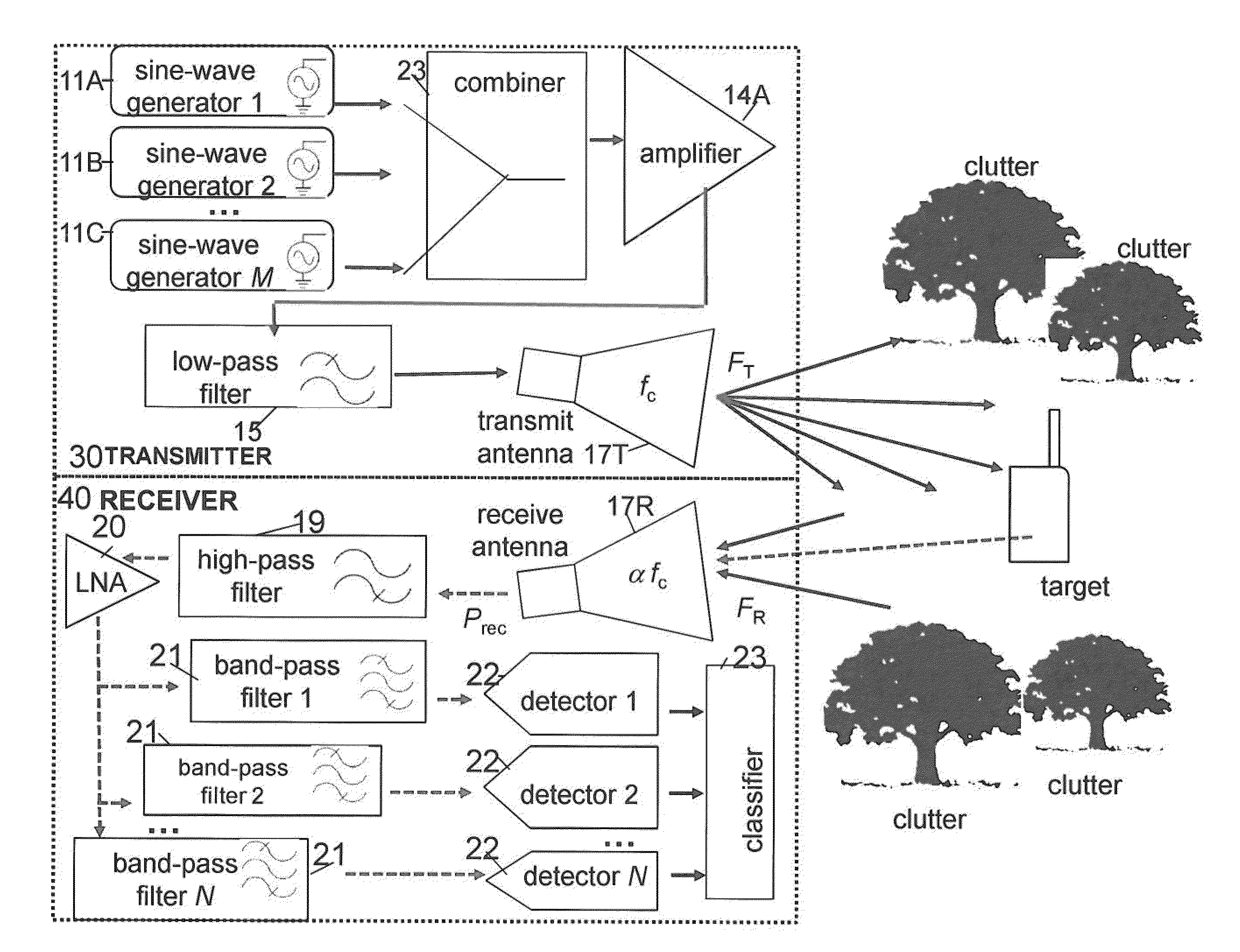
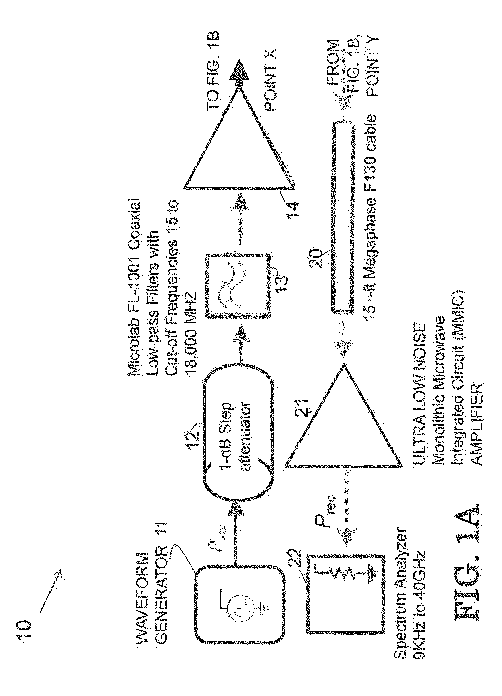
[0006]In order to minimize or eliminate system-generated nonlinear products whose frequencies are the same as those intended to be received, which degrade signal to noise ratio and obscure responses of electronic targets, a preferred embodiment system comprises a low-pass filter before the transmit antenna, and a high-pass filter and a bank of band-pass filters for the harmonic filter. The signal-to-interference ratio of the preferred embodiment system is improved by increasing the out-of-band rejection for the high-pass filter and for the band-pass filters. The sensitivity of the preferred embodiment system is improved by narrowing the bandwidth of each band-pass filter.
[0011]Optionally the predetermined selected frequency range of the return signal may be selected to maximize the response from a target based upon the emitting frequency of the target in the case of an RF emitting device. The system may optionally be used in conjunction with the operation of hospital medical equipment in order to avoid interference between unknown electronics devices and the medical equipment. In addition, the preferred embodiment system may be used in conjunction with the operation of a plane in order to avoid interference between the operation of detected electronics devices by the passengers and the operation of the plane's electronic equipment by the pilots.
[0014]Optionally, the high pass filter or filters may comprise an adjustable high pass filter and the receiver may further comprise an amplifier operatively connected to the at least one adjustable high pass filter for passage of the harmonics at the predetermined selected frequency range and a plurality of band pass filters operatively connected to the amplifier, each of the plurality of band pass filters may be limited to reception of a selected harmonic or selected combination of the at least two frequency components or harmonics. Thus, the frequency range to be detected by the detector may be restricted to recording a single harmonic or combination of harmonics to reduce error and increase detection capability, while maximizing efficiency.

Problems solved by technology

In the theater-of-operations, warfighters encounter threats that contain RF electronics.
Such RF electronic devices are generally small (man-portable) and typically buried or located close to the ground, making it difficult to distinguish from background clutter using traditional linear radar.

Method used


Image

  • Multitone Harmonic Radar and Method of Use
  • Multitone Harmonic Radar and Method of Use
  • Multitone Harmonic Radar and Method of Use

Examples


Embodiment Construction

[0035]The embodiments of the invention and the various features and advantageous details thereof are explained more fully with reference to the non-limiting embodiments that are illustrated in the accompanying drawings and detailed in the following description. It should be noted that the features illustrated in the drawings are not necessarily drawn to scale. Descriptions of well-known components and processing techniques are omitted so as to not unnecessarily obscure the embodiments of the invention. The examples used herein are intended merely to facilitate an understanding of ways in which the embodiments of the invention may be practiced and to further enable those of skill in the art to practice the embodiments of the invention. Accordingly, the examples should not be construed as limiting the scope of the embodiments of the invention. Rather, these embodiments are provided so that this disclosure will be thorough and complete, and will fully convey the scope of the invention ...


PUM


Abstract

A multitone nonlinear radar system (and a method of operating such a system) comprising a transmitter that transmits a signal comprising at least two predetermined frequency components; a receiver operating to receive return signals comprising harmonics of at least two predetermined frequencies, combinations of the at least two predetermined frequency components, and combinations of the harmonics of the at least two predetermined frequency components that are within a predetermined selected frequency range that has been predetermined to enable detection and / or classification of an electronic device; at least one antenna operating to transmit and receive electromagnetic radiation operatively connected to the transmitter and receiver; the receiver comprising at least one high pass filter for attenuating linear reflections at the two predetermined frequencies, and an analyzer;whereby electronic devices may be detected and identified by analyzing return signals within a predetermined frequency range.

Description

STATEMENT OF GOVERNMENT INTEREST[0001]The invention described herein may be manufactured, used, and licensed by or for the United States Government without the payment of royalties.BACKGROUND[0002]In the theater-of-operations, warfighters encounter threats that contain RF electronics. Such RF electronic devices are generally small (man-portable) and typically buried or located close to the ground, making it difficult to distinguish from background clutter using traditional linear radar.[0003]Whereas linear radar exploits the reflection from a target whose frequencies are the same as those transmitted, nonlinear radar exploits the electronic response from a target whose reflected frequencies are different from those transmitted. Reception of frequencies that are not part of the transmitted probe distinguishes the received signal from a linear return that can be produced by clutter and indicates the presence of an electronic circuit. For the warfighter, the presence of an electronic c...

Claims


Application Information

Patent Timeline
Patent Type & Authority Applications(United States)
IPC IPC(8): G01S7/02G01S13/42G01S7/41G01S13/04
CPCG01S7/02G01S13/04G01S7/41G01S7/023G01S13/42G01S7/354G01S7/414G01S13/887
Inventor MAZZARO, GREGORY JAMESMARTONE, ANTHONY F.
Owner US SEC THE ARMY THE
Why Eureka
Try Eureka