System and method for automated detection of lung nodules in medical images

a technology of medical images and detection methods, applied in the field of computed tomography imaging, can solve the problems of difficult visual detection of nodules, nodule detection is one of the more challenging visual detection tasks, and the role of diagnostic imaging is generally limited to visual inspection in clinical practice, so as to improve the accuracy of detecting nodules, and reduce false positive detections.

Active Publication Date: 2015-09-10
RGT UNIV OF CALIFORNIA
View PDF5 Cites 30 Cited by
  • Summary
  • Abstract
  • Description
  • Claims
  • Application Information

AI Technical Summary

Benefits of technology

[0015]Accordingly, an object of the present invention is the development of algorithms to improve accuracy in detecting nodules while ruling out normal anatomic structures. The present invention incorporates automated and interactive systems for lung image analysis, in particular a Euclidean distance transformation and segmentation approach based on watersheds that maintains a low level of false positive detections even while achieving high sensitivity for solid and faint ground glass nodules.
[0017]Another aspect is a method that provides improved segmentation and shape characterization of high intensity regions within the lung for better differentiation between nodules that tend to be spherical, and vessels that are generally more tubular. The improved discrimination of the present invention decreases the number of false positives arising from the CAD system, while maintaining sensitivity.

Problems solved by technology

However, the role of diagnostic imaging has generally been limited to visual inspection in clinical practice.
Nodule detection is one of the more challenging visual detection tasks in medical imaging.
Nodules may be difficult to detect visually on images because of low contrast, small size, or location of the nodule within an area of complicated anatomy such as the hilum.
Thinner slices and overlapping reconstruction intervals improve the longitudinal resolution, but require large data sets (700 or more cross-sectional images) to be generated, contributing to the difficulty of interpretation and potential for missed nodules.
However, CAD is not in widespread clinical use because of an inability to limit false positive detections, e.g., normal anatomy such as blood vessel or airway branches that are incorrectly detected by CAD as nodules.
These false positives not only take time to rule out, but some studies suggest that radiologists can incorrectly accept false positives, which in practice would lead to unnecessary workups.
If a method attempts to detect faint ground glass nodules (with intensity of around −700 HU) they typically generate too many false positives to be practical.

Method used


Image

  • System and method for automated detection of lung nodules in medical images
  • System and method for automated detection of lung nodules in medical images
  • System and method for automated detection of lung nodules in medical images

Examples


Embodiment Construction

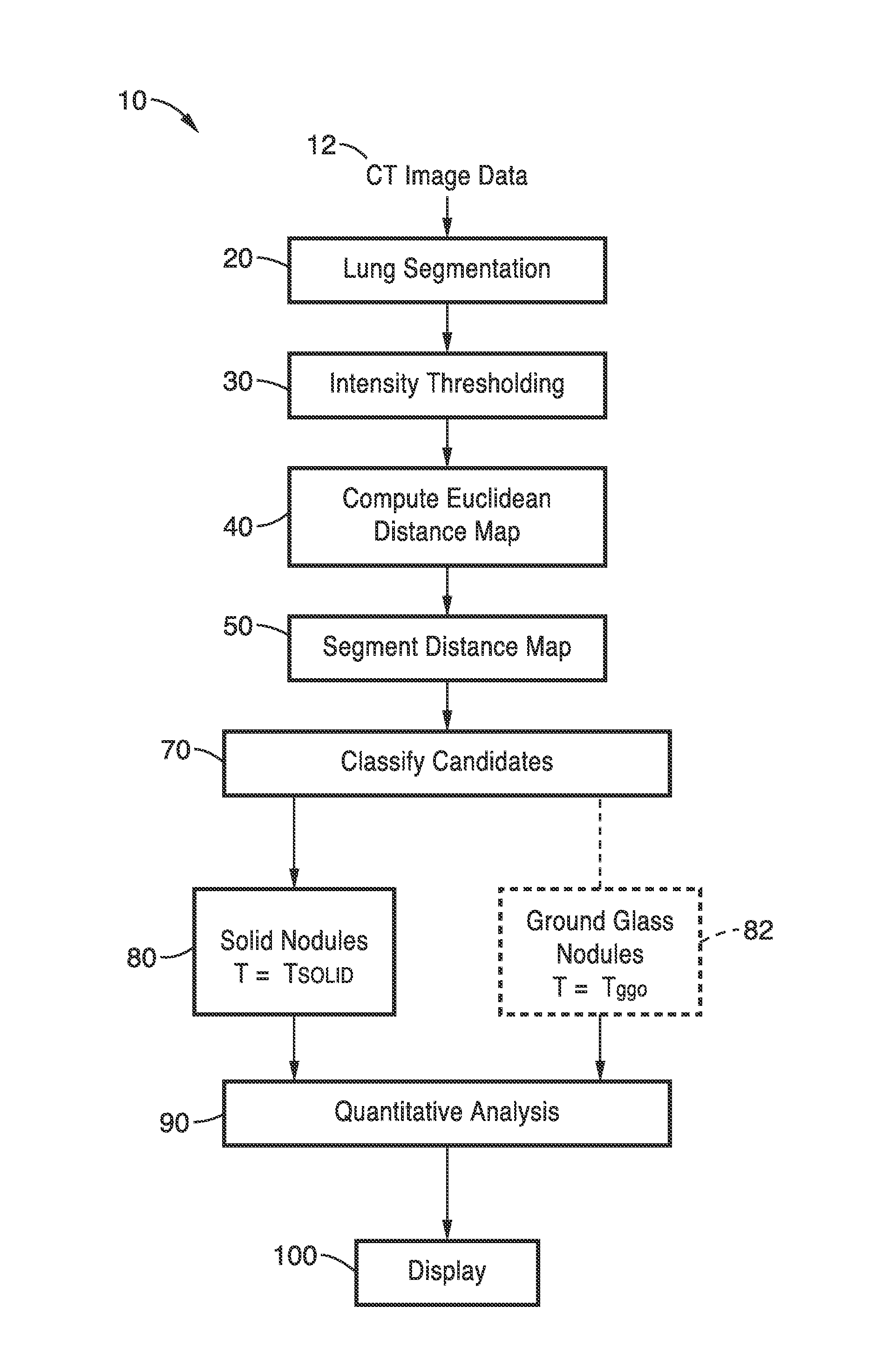
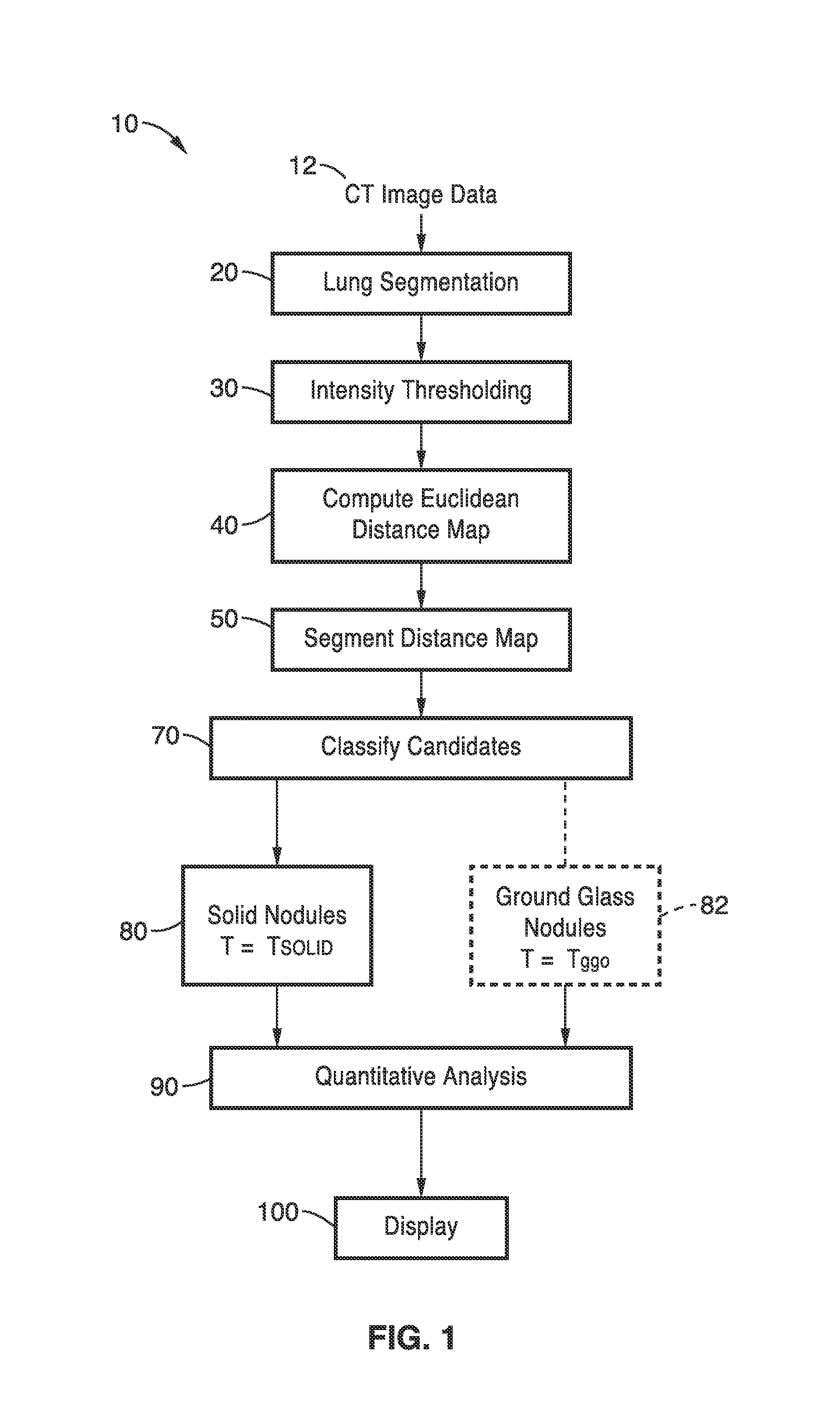
[0032]FIG. 1 illustrates an overview flow diagram of the lung nodule detection method 10 of the present invention. The scanned CT images 12 are first segmented at step 20. Next, intensity thresholding is performed is performed at step 30. This data is then used for performing Euclidean distance transformation at step 40. The distance map is then segmented at step 50. Candidates are classified at step 70. Solid nodules are detected at step 80 based on threshold T=Tsolid. For detection of ground class nodules at step 82, intensity thresholding step 30, Euclidean distance transformation step 40, and distance map segmentation step 50 are repeated based on threshold T=Tggo (see FIG. 3, FIG. 4 and FIG. 5). At step 90, quantitative assessment may be performed for regions of interest (ROI's) identified as nodules. The detected nodules may then be displayed as overlays in step 100.

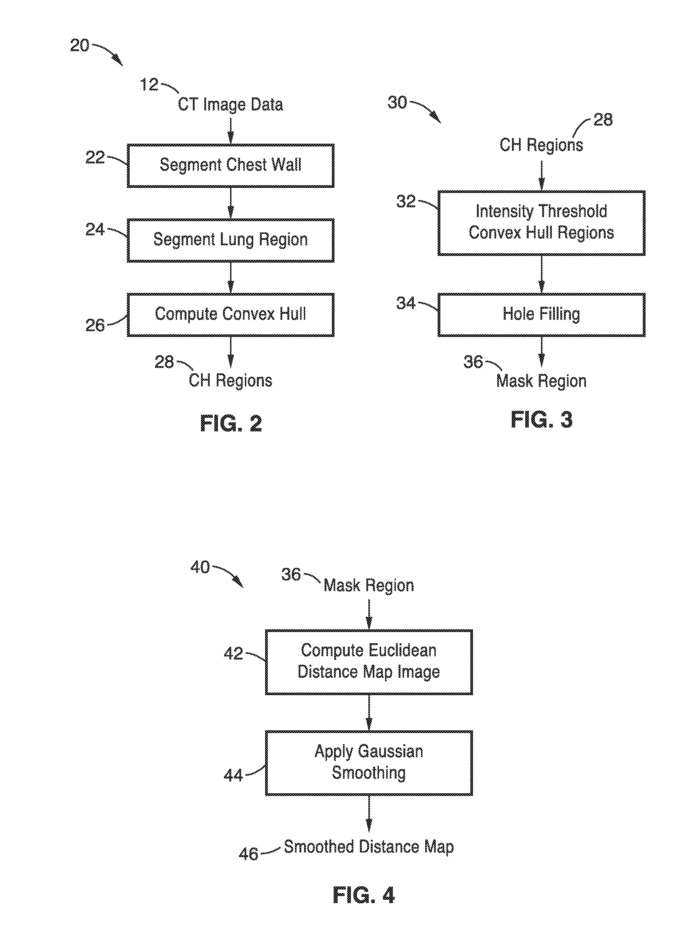
[0033]FIG. 2 is a detailed flow diagram of the lung segmentation step 20 of

[0034]FIG. 1, which incorporates regi...


PUM


Abstract

A system and method for automatically segmenting a computed tomography (CT) image of a patient's lung. The method includes the steps of segmenting the CT image to acquire one or more lung regions, intensity thresholding the lung regions to generate a mask region comprising high-intensity regions corresponding to anatomical structures within the lung regions, computing a Euclidean distance map of the mask region, performing watershed segmentation of the Euclidean distance map to generate one or more sub-regions, identifying a seed point for each sub region, growing candidate regions from the seed point of each sub-region, and classifying one or more candidate regions as a lung nodule based on one or more geometric features of the candidate regions.

Description

CROSS-REFERENCE TO RELATED APPLICATIONS[0001]This application is a 35 U.S.C. §111(a) continuation of PCT international application number PCT / US2013 / 029646 filed on Mar. 7, 2013, incorporated herein by reference in its entirety, which claims priority to, and the benefit of, U.S. provisional patent application Ser. No. 61 / 700,592 filed on Sep. 13, 2012, incorporated herein by reference in its entirety. Priority is claimed to each of the foregoing applications.[0002]The above-referenced PCT international application was published as PCT International Publication No. WO 2014 / 042678 on Mar. 20, 2014, which publication is incorporated herein by reference in its entirety.STATEMENT REGARDING FEDERALLY SPONSORED RESEARCH OR DEVELOPMENT[0003]This invention was made with Government support under CA088973, awarded by the National Institutes of Health. The Government has certain rights in the invention.INCORPORATION-BY-REFERENCE OF COMPUTER PROGRAM APPENDIX[0004]Not ApplicableNOTICE OF MATERIAL...

Claims


Application Information

Patent Timeline
Patent Type & Authority Applications(United States)
IPC IPC(8): G06T7/00G06K9/62G06K9/46G06K9/52
CPCG06T7/0012G06K9/52G06T7/0081G06K2009/4666G06K9/46G06T2207/30064G06K9/6267A61B6/032A61B6/12A61B6/50A61B6/5217G06T2207/10081G06T2207/20152G06T2207/30096G06T2200/04G06T2207/20041G06T7/11G06T7/155G06T7/62G06T7/187G06T7/136G06F18/24
Inventor BROWN, MATTHEW S.
Owner RGT UNIV OF CALIFORNIA
Why Eureka
Try Eureka