Fault detection in induction machines

a fault detection and induction machine technology, applied in the direction of dynamo-electric machine testing, instruments, measurement devices, etc., can solve the problems of excessive vibration, excessive loss of revenue, and permanent damage to the machin

Active Publication Date: 2015-09-17
ROLLS ROYCE PLC
View PDF26 Cites 38 Cited by
  • Summary
  • Abstract
  • Description
  • Claims
  • Application Information

AI Technical Summary

Benefits of technology

[0024]The present invention aims to provide a method and apparatus which reliably provides

Problems solved by technology

If these faults are undetected at early stages then these faults can lead to electrical or mechanical failure, which can cause permanent damage to the machine, and potential excessive loss of revenue.
The consequences of this fault include excessive vibrations, poor starting performances, torque fluctuation, and high thermal stress.
If this fault remains undetected it may lead to potentially catastrophic failures.
A rotor fault such as a BRB fault introduces asymmetry in the machine current, which produces a backward rotating field, rotating at a slip frequency of the machine.
However, these prior art methods have significant disadvantages.
The frequency of the BRB fault signature (which is a function of slip) is close to the fundamental supply

Method used


Image

  • Fault detection in induction machines
  • Fault detection in induction machines
  • Fault detection in induction machines

Examples


Embodiment Construction

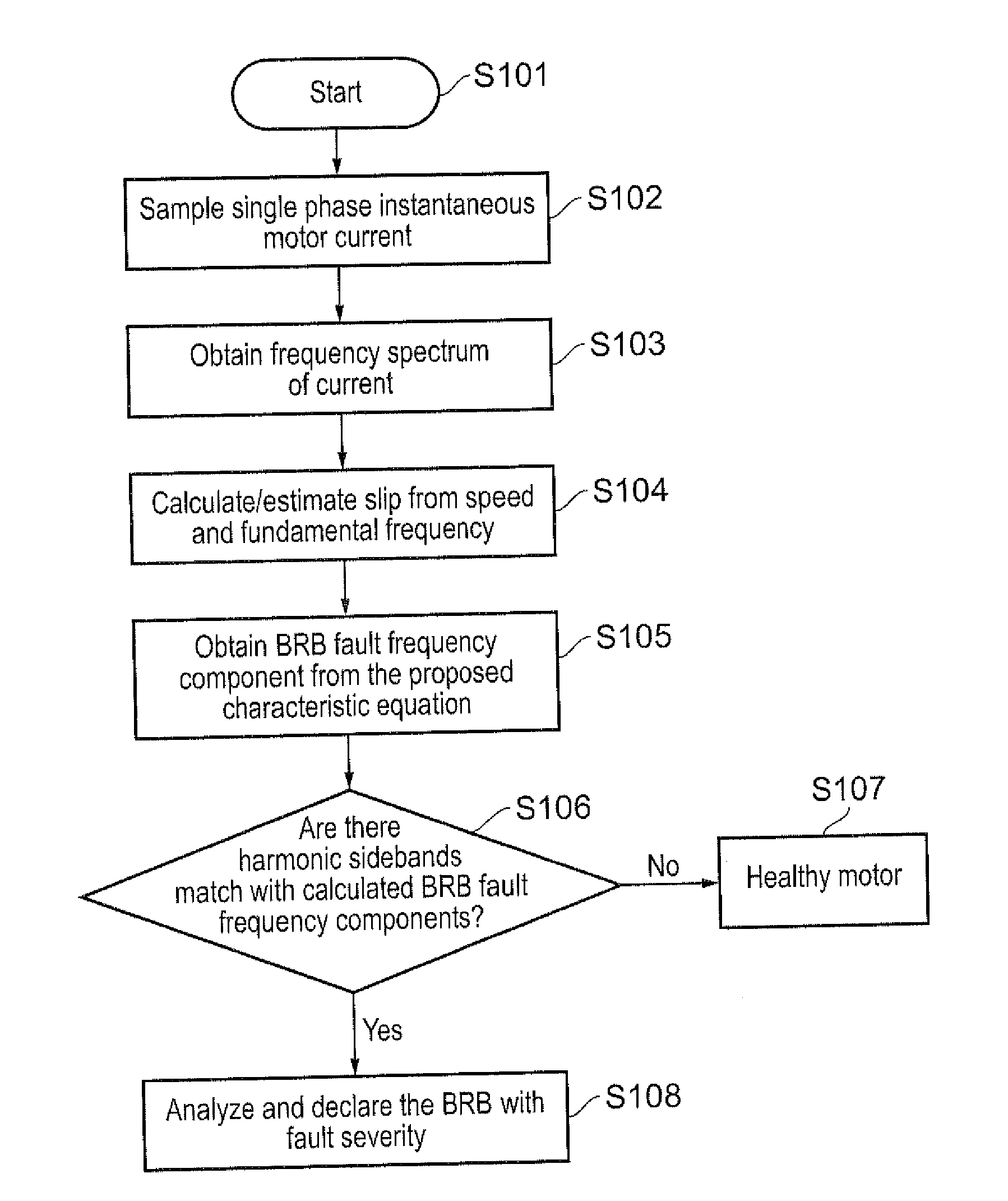
[0087]In an aspect, the present invention provides a new equation to detect faults, e.g. BRB faults, in electrical machines such as induction motors. The new equation identifies the sideband frequencies which are characteristic fault frequency components of a BRB fault. But, unlike the prior art classical equation (equation (1) above) used in existing techniques, the new equation helps to identify the fault frequency components (the sidebands) of harmonics of the fundamental supply frequency, other than the fundamental supply frequency itself.

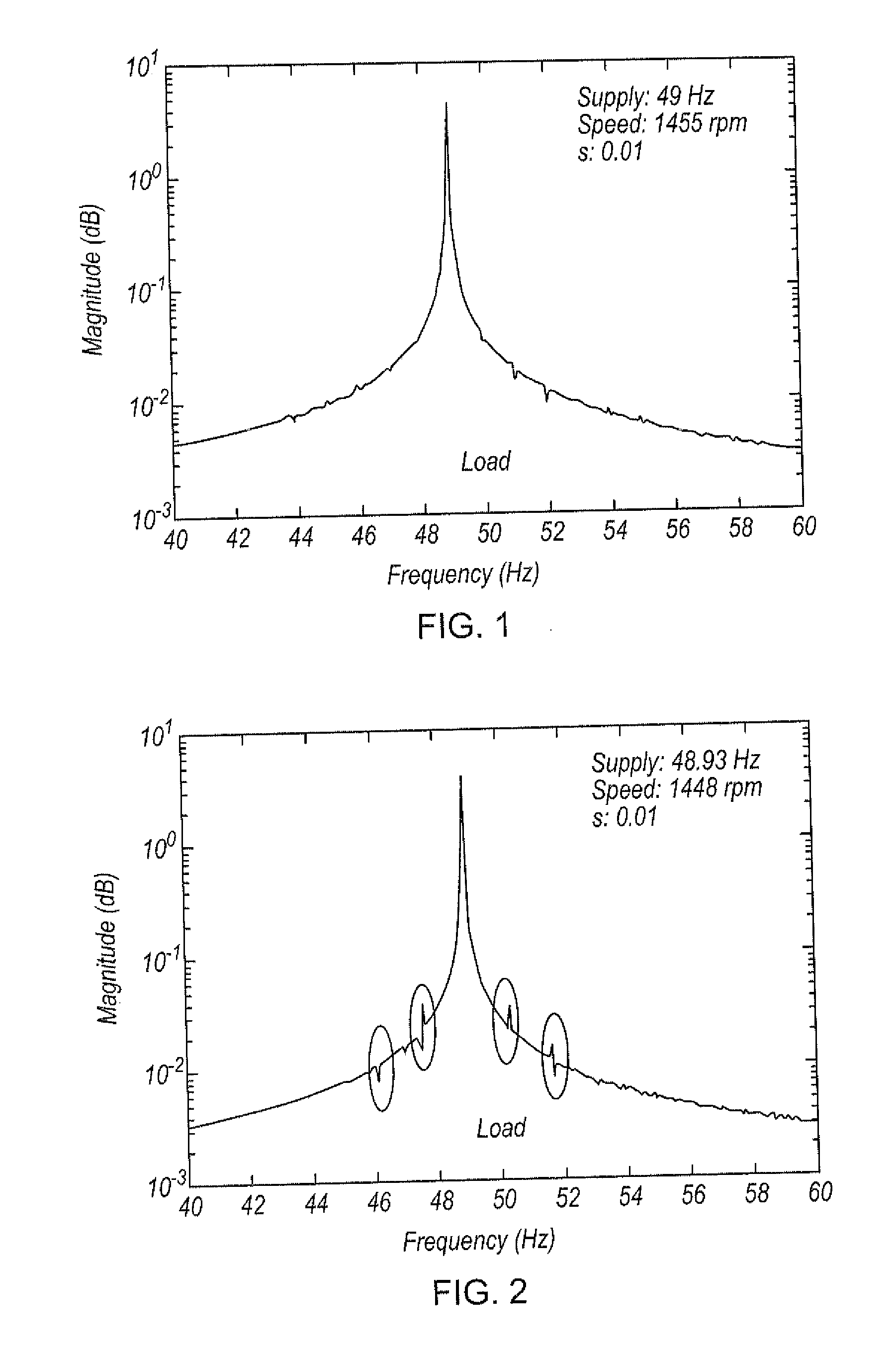
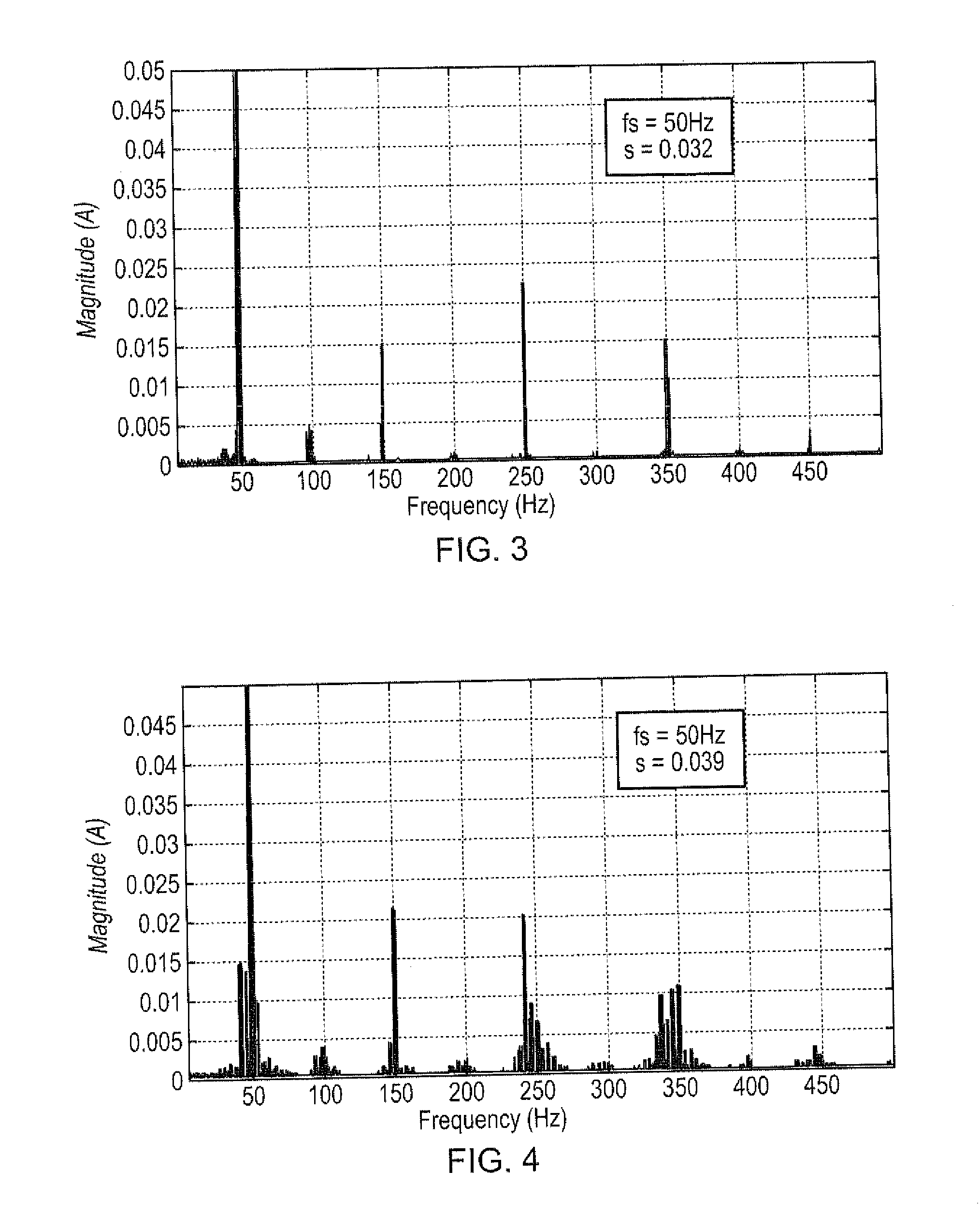
[0088]The present invention provides several advantages over the prior art, such as reliable fault detection at low frequency resolution of current frequency spectrum, low slip (e.g. low load), and at low fault severity. Furthermore, the present invention is applicable to single phase current measurements (in addition to multi-phase current measurements), which has the added advantage of requiring less computational resource, and means the inve...


PUM


Abstract

A method of detecting a fault in an induction machine having one or more windings arranged to draw current at a supply frequency, the method including: performing a process of judging whether a respective sideband of one or more selected harmonics of the supply frequency exists at a predetermined fault frequency in a signal in the one or more windings; and determining that a fault has occurred if the judgement is positive; wherein in the judging process each of the selected harmonics of the supply frequency is a harmonic frequency of the supply frequency other than the supply frequency itself.

Description

FIELD OF THE INVENTION[0001]The present invention relates to detecting faults in induction machines: in particular, but not exclusively, to the detection of broken rotor bar (BRB) faults in induction machines, such as induction motors.BACKGROUND OF THE INVENTION[0002]Electrical machines are widely used in industrial applications. More than 80% of rotating machines worldwide are induction machines, and they are responsible for consuming around 50% of the total power generated in industrialized nations.[0003]Induction machines are also used in safety and mission critical applications such as actuators in aircraft and propulsion motors in marine vessels.[0004]It is therefore important to improve the reliability, and hence availability for function, of induction machines, e.g. motors, by early and reliable detection of faults. Electrical stress and thermal stress are the primary reasons for faults in induction machines. If these faults are undetected at early stages then these faults ca...

Claims


Application Information

Patent Timeline
IPC IPC(8): G01R31/34G01R23/02
CPCG01R23/02G01R31/34G01R31/343
Inventor ATHIKESSAVAN, SUBASH C.NADARAJAN, SIVAKUMARGUPTA, AMIT KUMARPANDA, SANJIB K.
Owner ROLLS ROYCE PLC
Why Eureka
Try Eureka