Active rectifier and wireless power receiving apparatus using the same that can reduce reverse current leakage

a technology of active rectifiers and wireless power receiving devices, which is applied in the direction of transformers, inductances, and conversions with intermediate conversion to dc, can solve the problems of low efficiency, harmful to the human body, and short distance between power transmitters and power receivers, so as to reduce reverse current leakage

Active Publication Date: 2015-09-17
SKAI CHIPS
View PDF6 Cites 262 Cited by
  • Summary
  • Abstract
  • Description
  • Claims
  • Application Information

AI Technical Summary

Benefits of technology

[0011]At least some embodiments of the present invention are directed to the provision of an active rectifier capable of reducing a reverse current leakage, and a wireless power reception apparatus using the same.
[0012]At least some embodiments of the present invention are directed to the provision of an active rectifier capable of reducing reverse current leakage using a delay compensation means for compensating a delay time to take for active elements to turn off, and a wireless power reception apparatus using the same.
[0017]The synchronization control unit may be configured to: compensate for the delay time of the comparator for detecting zero-crossing time of the AC input so as to switch the first and the second switches; and compensate for delay time of the comparator for detecting zero-crossing of the AC input and delay time of one of the first and second level shifters, so as to switch the third and fourth switches.
[0021]In accordance with another aspect of the present invention, there is provided a wireless power reception apparatus, including: a resonant reception coil for receiving a radio signal, so as to generate a waveform of an AC input; an active rectifier for comprising first and fourth switches turned on while a voltage of the AC input is negative so as to apply a current of the AC input to a rectifying capacitor and second and third switches turned on while a voltage of the AC input is positive so as to apply a current of the AC input to the rectifying capacitor, and for compensating for a delay time of a comparator for detecting zero-crossing of the AC input so as to switch the first to fourth switches; and a low loss regulator for generating a DC voltage from a voltage charged in the rectifying capacitor.

Problems solved by technology

Wireless power transmission technology based on electromagnetic waves initially started with technology for sending power over a long or short distance in such a manner that a power transmitter sends electromagnetic waves having high energy in a desired direction and a power receiver receives the transmitted electromagnetic waves, and has not overcome the problem in which it has very low efficiency and is harmful to the human body.
However, distance allowable between power transmitter and power receiver is very short, a large amount of heat is generated, usability is bad because charging efficiency highly varies depending on the locations of the power transmitter and the power receiver, and, above all, the amount of transmission power is limited.
Passive rectifiers using diode bridges suffer from loss in peak voltage due to voltage drop generated by diodes.
Such leaking reverse current degrades efficiency.
Although such reverse current can be reduced by fully turning off the diode-connected active elements depending on sections of AC input waveform, reverse current may still occur during a delay time because it takes time to turn off the active elements.

Method used


Image

  • Active rectifier and wireless power receiving apparatus using the same that can reduce reverse current leakage
  • Active rectifier and wireless power receiving apparatus using the same that can reduce reverse current leakage
  • Active rectifier and wireless power receiving apparatus using the same that can reduce reverse current leakage

Examples


Embodiment Construction

[0035]With regard to embodiments of the present invention disclosed herein, specific structural and functional descriptions are given merely for the purpose of illustrating the embodiments of the present invention. Embodiments of the present invention may be practiced in various forms, and the present invention should not be construed as being limited to embodiments disclosed herein.

[0036]Embodiments of the present invention will be described in detail below with reference to the accompanying drawings. The same reference numerals will be used to denote the same components throughout the accompanying drawings, and redundant descriptions of the same components will be omitted.

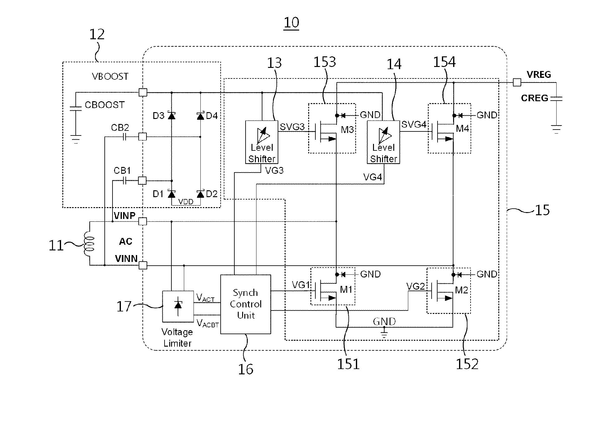
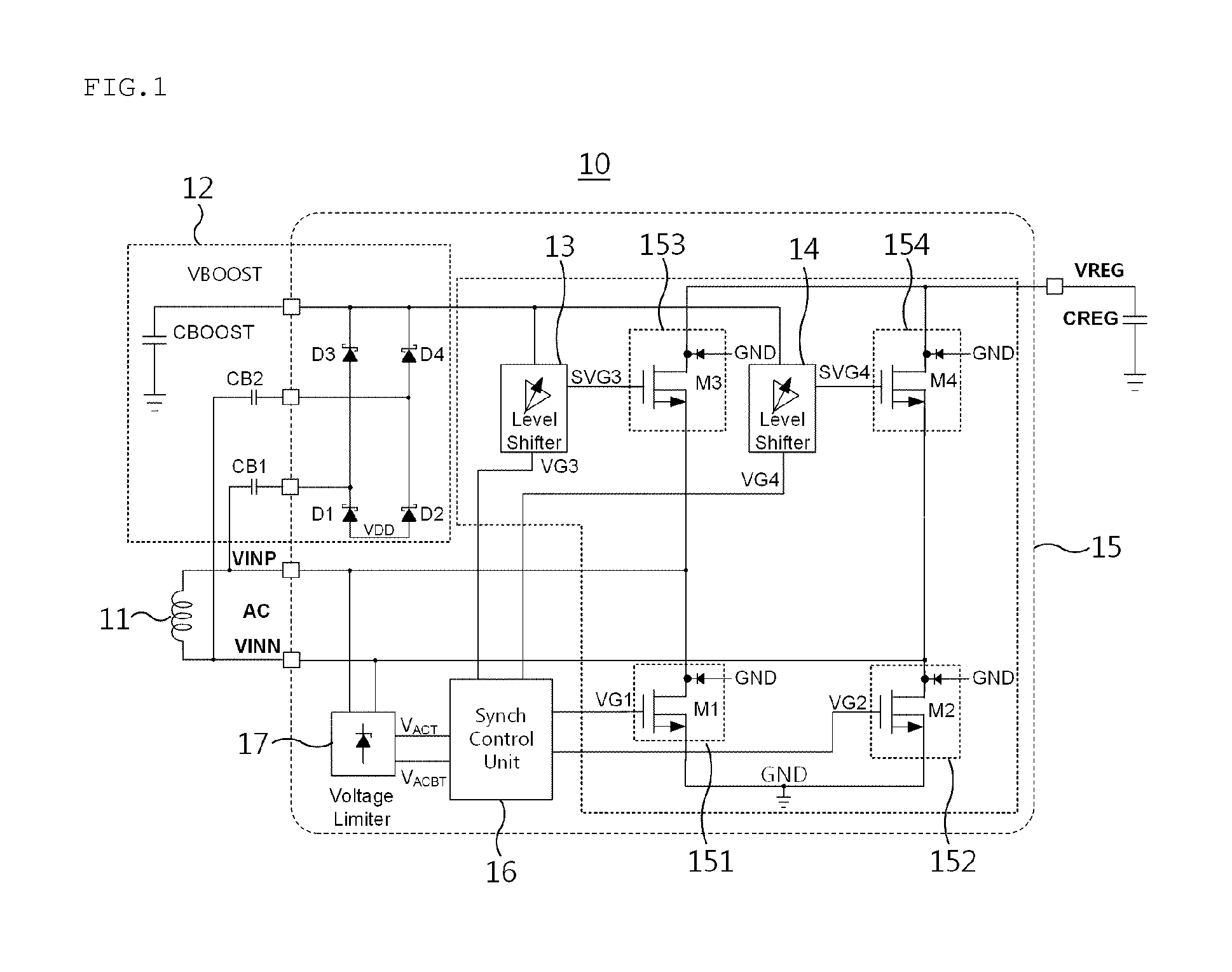
[0037]FIG. 1 is a conceptual diagram illustrating an active rectifier according to an embodiment of the present invention.

[0038]Referring to FIG. 1, the active rectifier 10 may include a resonant reception coil 11, a voltage booster 12, first and second level shifters 13 and 14, a synchronous rectification circui...


PUM


Abstract

An active rectifier and a wireless power reception apparatus using the same are disclosed herein. The active rectifier includes first and fourth switches, second and third switches, and a synchronization control unit. The first and fourth switches are turned on while the voltage of an alternating current (AC) input is negative, and apply the current of the AC input to a rectifying capacitor. The second and third switches are turned on while a voltage of the AC input is positive, and apply the current of the AC input to the rectifying capacitor. The synchronization control unit compensates for the delay time of the comparator for detecting zero-crossing of the AC input so as to switch the first to fourth switches.

Description

BACKGROUND[0001]1. Technical Field[0002]The present invention relates to wireless power transmission technology and, more particularly, to a rectifier in a wireless power reception apparatus.[0003]2. Description of the Related Art[0004]Wireless power transmission technology based on electromagnetic waves initially started with technology for sending power over a long or short distance in such a manner that a power transmitter sends electromagnetic waves having high energy in a desired direction and a power receiver receives the transmitted electromagnetic waves, and has not overcome the problem in which it has very low efficiency and is harmful to the human body.[0005]Wireless power transmission technology using magnetic induction scheme has been attempted since the discovery of a magnetic induction phenomenon, and includes many commercialized cases. However, distance allowable between power transmitter and power receiver is very short, a large amount of heat is generated, usability...

Claims


Application Information

Patent Timeline
Patent Type & Authority Applications(United States)
IPC IPC(8): H02J5/00H02M7/217
CPCH02M7/217H02J5/005H02M7/219H02M7/2195Y02B70/10H02J50/12H02M1/0054
Inventor LEE, KANG YOONJANG, JAE HYUNGPARK, HYUNG GUCHUN, JOO YOUNG
Owner SKAI CHIPS
Why Eureka
Try Eureka