Temperature measurement and calibration circuit, passive radio frequency identification tag and method for measuring temperature

a temperature measurement and calibration circuit technology, applied in the field of radio frequency identification, can solve the problems of large packaging volume, high cost of chips, inability of temperature sensors to perform temperature measurement well in warehouse management, food and healthcare, etc., and achieve the effect of eliminating problems, high measurement accuracy and ensuring accuracy

Active Publication Date: 2015-09-24
EXCELIO TECH SHENZHEN +1
View PDF2 Cites 11 Cited by
  • Summary
  • Abstract
  • Description
  • Claims
  • Application Information

AI Technical Summary

Benefits of technology

[0029]The present invention has the following advantages: the reference voltage generator circuit of the radio frequency identification tag generates two paths of reference voltage signals, i.e., an upper reference voltage value limit and a lower reference voltage value limit, which do not change with temperature, then calibrates the upper reference voltage value limit and the lower reference voltage value limit so that the upper reference voltage value limit of all tags to be measured is calibrated to a uniform upper voltage value limit and the lower reference voltage value limit thereof is calibrated to a uniform lower voltage value limit, and eliminates the problem of different generated reference voltages of tags due to the fluctuation of various non-ideal factors and process deviation; meanwhile, the temperature measurement voltage generator circuit of each tag generates a calibration voltage value under a uniform calibration temperature, and after the calibration voltage value is subjected to translational calibration, the calibration voltage values of all tags to be measured are equal, so that the consistency of temperature values measured by using different tags under the fluctuation of various non-ideal factors and different process deviations is ensured. Further, by amplifying the temperature measurement voltage value generated during the actual measurement so that this temperature measurement voltage value is allowed to be between the upper reference voltage value limit and the lower reference voltage value limit and performing analog-to-digital conversion on this temperature measurement voltage value, and by performing equalization on the digital signal, an accurate temperature value corresponding to this voltage value may be obtained. In this way, the accuracy of temperature measurement is ensured. The circuit and tag provided by the present invention may be widely applied to ambient temperature detection, animal temperature detection, cold chain temperature detection or other fields, and have high accuracy of measurement.

Problems solved by technology

In an integrated electronic system, such individual temperature sensor chips have the characteristics of high cost, large packaging volume and the like.
As a result, the application fields of such temperature sensors are limited.
For example, such temperature sensors are unable to perform temperature measurement well in warehouse management, food and healthcare, animal management or other fields.
During the temperature measurement performed by using a passive RFID tag, on one hand, as each module of the passive RFID tag is limited in restraining the AC disturbance to the power supply voltage, the node voltage of each module will be modulated by the disturbed power supply voltage to varying degrees, and such modulation disturbance, in the nature of noise, will impede the accuracy of temperature measurement performed by using the passive RFID tag; and on the other hand, during the manufacturing of a passive RFID tag by a semiconductor chip manufacturer, as the manufactured RFID tag is subjected to the processes, the performance of the circuits will be fluctuated to varying degrees.
Such fluctuation directly results in a large range of errors and inconsistency, in converting a physical quantity indicative of temperature, of different RFID tags manufactured by a same semiconductor chip manufacturing process.
Thus, it is unable to ensure the consistency of temperature measurement of passive RFID tags.
For batch products, this is a fatal weakness which directly affects whether or not the products may be introduced to the market and accepted by users eventually.

Method used


Image

  • Temperature measurement and calibration circuit, passive radio frequency identification tag and method for measuring temperature
  • Temperature measurement and calibration circuit, passive radio frequency identification tag and method for measuring temperature
  • Temperature measurement and calibration circuit, passive radio frequency identification tag and method for measuring temperature

Examples


Embodiment Construction

[0037]The technical solutions in the embodiments of the present invention will be clearly and completely described as below with reference to the drawings in the embodiments of the present invention. Apparently, the described embodiments are merely some but not all of embodiments of the present invention. All other embodiments obtained by a person of ordinary skill in the art on the basis of the embodiments of the present invention without any creative effort shall fall into the protection scope of the present invention.

[0038]Before describing the embodiments of the present invention, some keywords involved in the embodiments of the present invention are to be explained. “Coupled to” as used in the embodiments of the present invention means that two connecting endpoints are in direct or indirect connection.

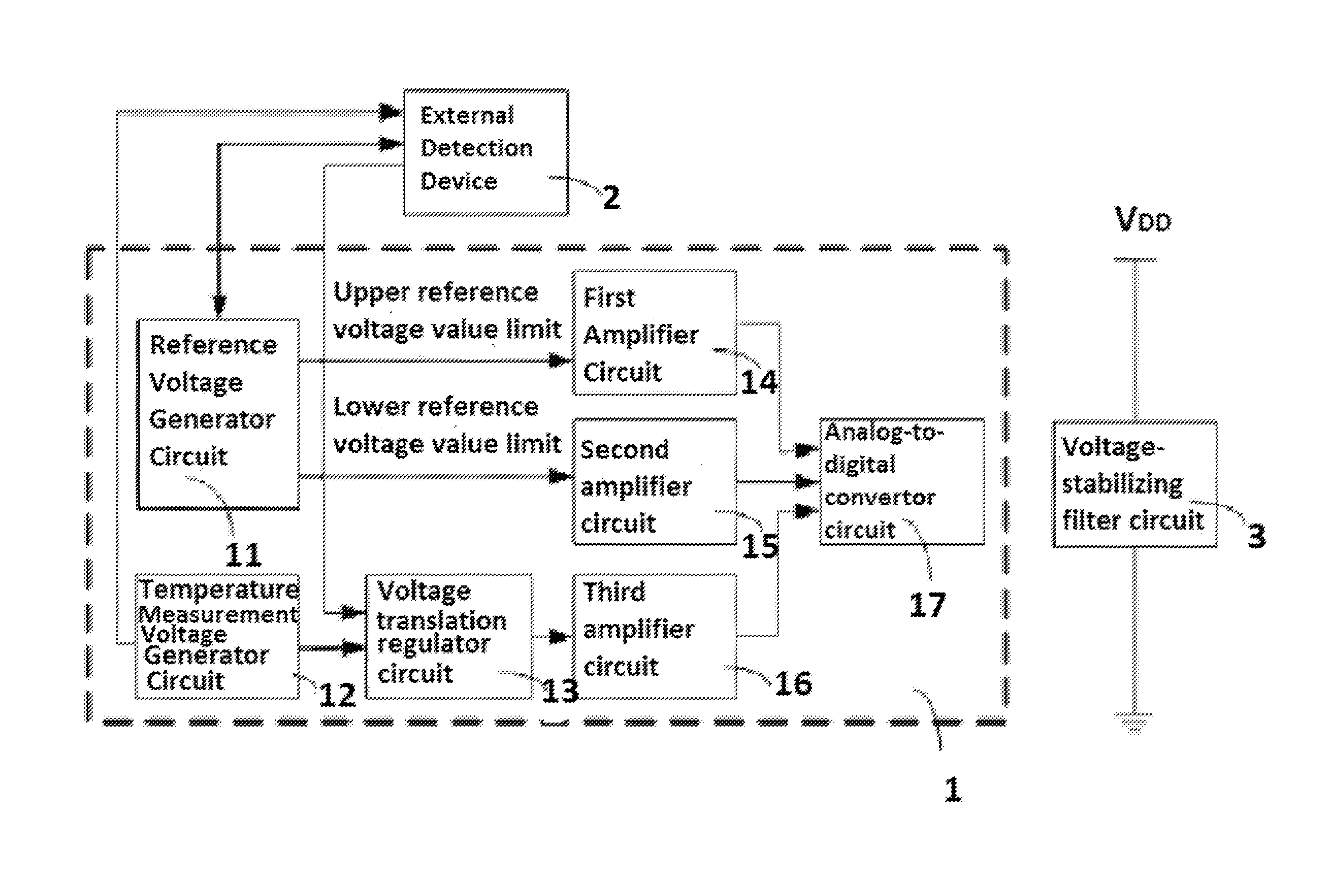
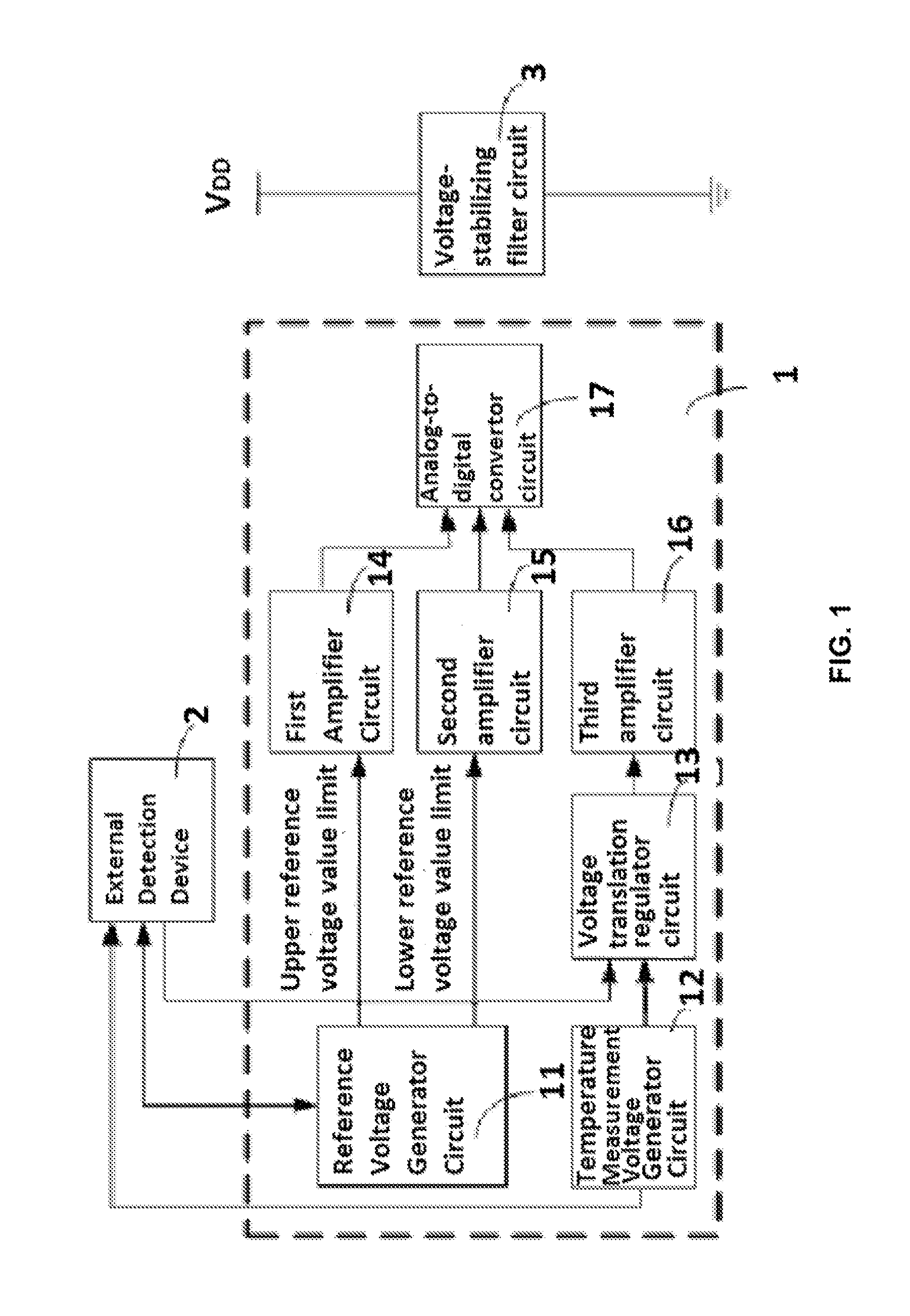
[0039]As shown in FIG. 1, a general structure block diagram of a circuit according to the present invention is shown. The present invention provides a temperature measurement and ...


PUM

PropertyMeasurementUnit
temperatureaaaaaaaaaa

Abstract

The present invention relates to the field of radio frequency identification, in particular to a temperature measurement and calibration circuit and a passive radio frequency identification tag. Meanwhile, the present invention further relates to a method for performing temperature measurement by using the tag. The temperature measurement and calibration circuit of the tag generates an upper reference voltage value limit and a lower reference voltage value limit, which do not change with temperature, then calibrates the upper reference voltage value limit and the lower reference voltage value limit to a uniform upper voltage value limit and a uniform lower voltage value limit, and eliminates the problem of different reference voltages of tags due to the power supply voltage fluctuation and process deviation. Meanwhile, a temperature measurement voltage generator circuit of the tag generates a calibration voltage value under a uniform calibration temperature. After the calibration voltage value is subjected to translational calibration, the calibration voltage values of the tags to be measured are equal, so that the consistency of temperature values of different tags is ensured. The circuit and tag provided by the present invention may be widely applied to ambient temperature detection, animal temperature detection, cold chain temperature detection or other fields, and have high accuracy of measurement.

Description

CROSS-REFERENCE TO RELATED APPLICATIONS[0001]This application is a continuation-in-part of International Patent Application No. PCT / CN2013 / 073895 with an international filing date of Apr. 8, 2013, designating the United States, now pending, and further claims priority benefits to Chinese Patent Application No. 201210352087.X filed Sep. 20, 2012. The contents of all of the aforementioned applications, including any intervening amendments thereto, are incorporated herein by reference.TECHNICAL FIELD[0002]The present invention relates to the field of radio frequency identification, in particular to a temperature measurement and calibration circuit and a passive radio frequency identification tag. Meanwhile, the present invention further relates to a method for performing temperature measurement by using the passive radio frequency identification tag.BACKGROUND OF THE PRESENT INVENTION[0003]As a contactless automatic identification technology, Radio Frequency Identification (RFID), havi...

Claims


Application Information

Patent Timeline
Patent Type & Authority Applications(United States)
IPC IPC(8): G01K15/00G06K19/07
CPCG06K19/0717G01K15/005G01K1/024
Inventor WU, PATRICK BIANWANG, XINGYIZHOU, LINGLIHAN, FUQIANGQI, SHEHULUO, YUANMING
Owner EXCELIO TECH SHENZHEN
Why Eureka
Try Eureka