
Alignment plate apparatus and system and method of use

a technology of aligning plate and apparatus, which is applied in the field of aligning plate apparatus and system and method of use, can solve the problems that the placement of implants or the reduction of bone fragments may not be as close as the surgeon wishes, and the acetabulum may be deteriorated

Active Publication Date: 2015-10-01
ORTHOGRID SYST HLDG LLC
View PDF0 Cites 7 Cited by
  • Summary
  • Abstract
  • Description
  • Claims
  • Application Information

AI Technical Summary

Benefits of technology

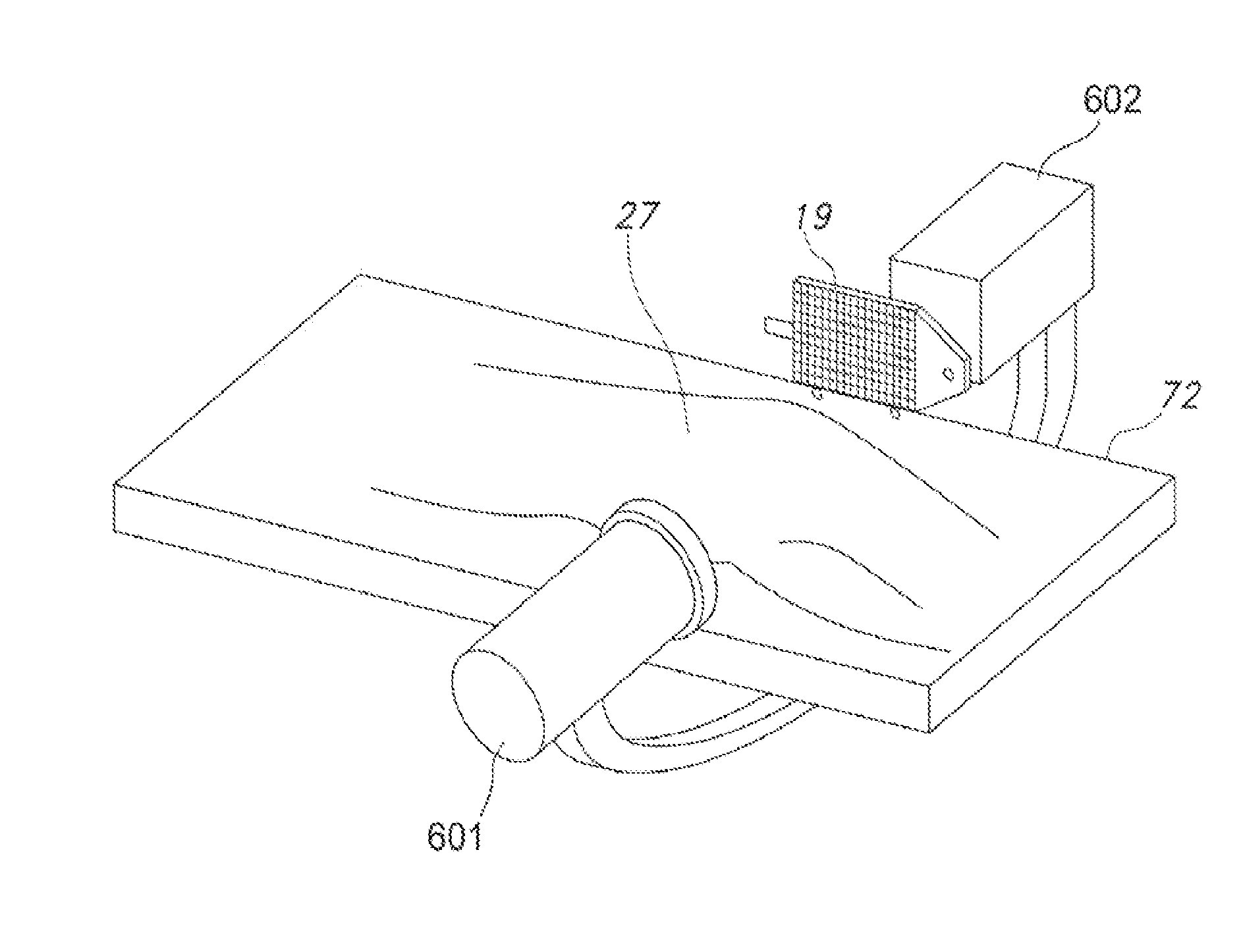
The present invention is a system and method for assisting in the placement of an implant in a patient. The system includes a camera for capturing an operative image of the patient's body where the implant is to be operated on, and a reference image of the contra lateral side of the patient's body. A computer program then identifies anatomical markers in the reference and operative images and produces an overlaid image by aligning the markers. The program also determines measurements that are critical to the operation of the implant and generates a report or provides the measurements continuously to the surgeon for decision-making. The technical effect of the invention is to improve the accuracy and precision of implant placement in surgery.

Problems solved by technology

However even with intraoperative fluoroscopic guidance, the placement of an implant or the reduction of a bone fragment may still not be as close as desired by the surgeon.
For example, mal-positioning of the acetabular component during hip arthroplasty can lead to problems.
Unfortunately, the position of the patient's pelvis varies widely during surgery and from patient to patient.
Unfortunately, in a fracture scenario, the original anatomical position of these bone fragments has been compromised and their natural relationship with the correct anatomy is uncertain and requires the surgeon to use his / her best judgment in order to promote a successful repair and subsequent positive outcome.
However, it has been suggested that the acetabulum may be deteriorated due to arthritis.

Method used


Image

  • Alignment plate apparatus and system and method of use
  • Alignment plate apparatus and system and method of use
  • Alignment plate apparatus and system and method of use

Examples


Embodiment Construction

[0064]The present invention may be understood more readily by reference to the following detailed description of the invention. It is to be understood that this invention is not limited to the specific devices, methods, conditions or parameters described herein, and that the terminology used herein is for the purpose of describing particular embodiments by way of example only and is not intended to be limiting of the claimed invention. Also, as used in the specification including the appended claims, the singular forms “a,”“an,” and “the” include the plural, and reference to a particular numerical value includes at least that particular value, unless the context clearly dictates otherwise. Ranges may be expressed herein as from “about” or “approximately” one particular value and / or to “about” or “approximately” another particular value. When such a range is expressed, another embodiment includes from the one particular value and / or to the other particular value. Similarly, when valu...


PUM


Abstract

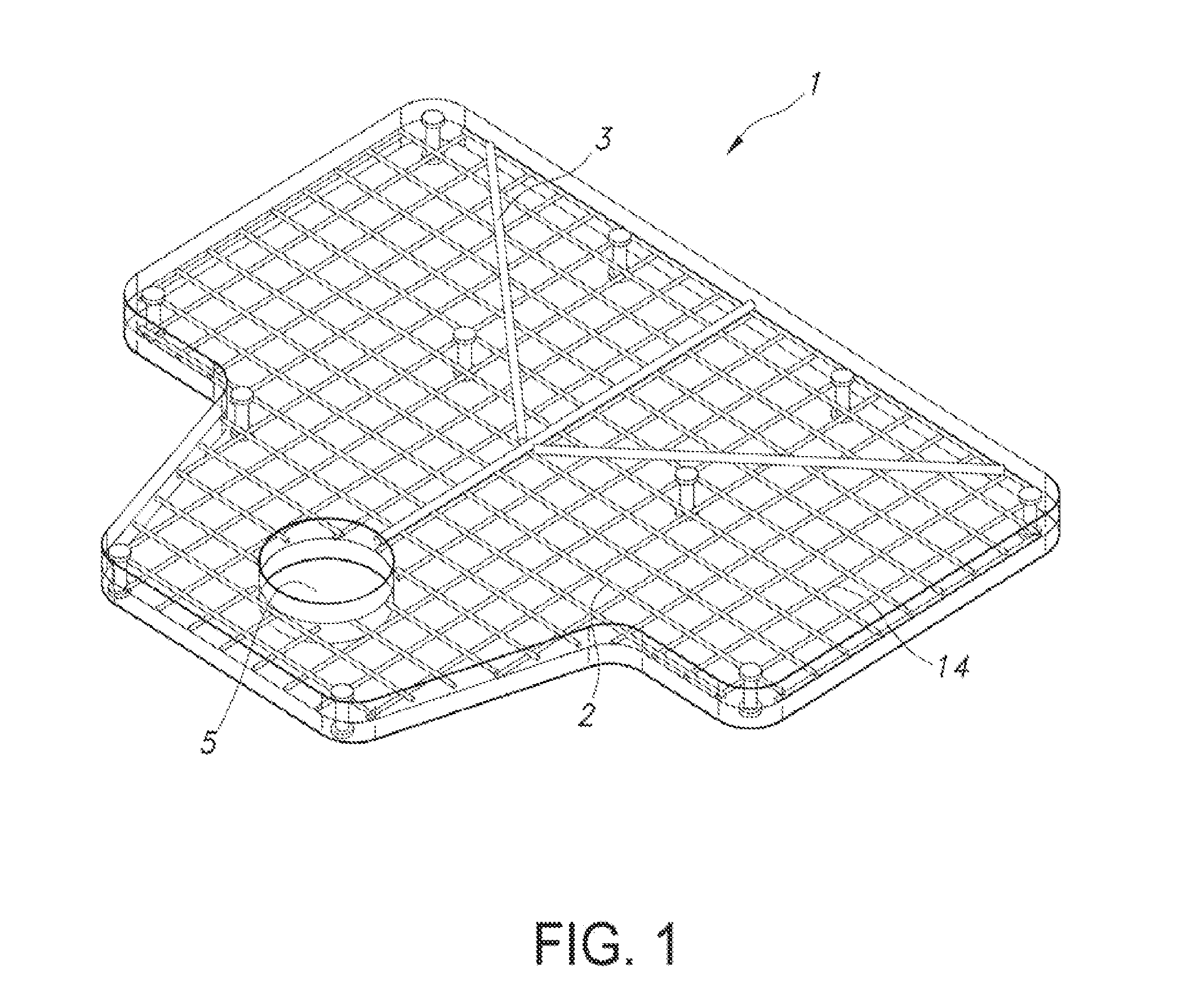
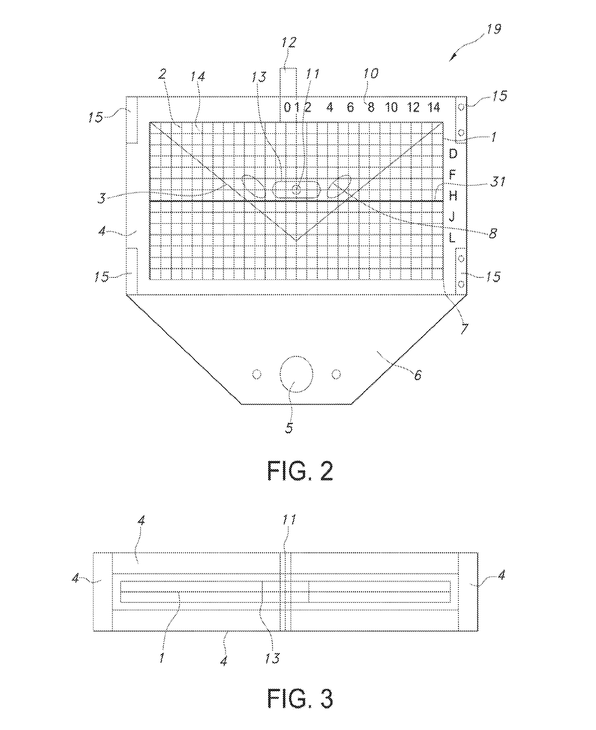
A computer implemented system for adjusting the placement of an implant in a patient through the use of a dimensioned grid template placed relative to patient anatomy on a fluoroscopic machine and a method to digitally quantify alignment parameters is provided. This system can be used for determining: 1) leg length, offset, and cup position during arthroplasty replacement surgery; 2) fracture reduction / correction position during trauma procedures and 3) an apparatus to be used for defomity correction planning is provided; 4) placement and positioning of instruments and implants relative to bone and anatomical architecture; 5) bone anatomy boundary parameter identification relative to reaming and cutting landmarks of bone.

Description

[0001]The present invention relates to a computer implemented system for positioning and adjusting the placement of an implant or instruments or bone fragment or reconstruction of anatomical bone architecture in a patient through the use of a dimensioned radio-opaque pre-dimensioned template placed relative to a patient's anatomy visible intraoperatively via the use of a fluoroscopic machine and a method to digitally quantify the alignment and placement parameters in any and all musculoskeletal applications such as joint arthroplasty, and trauma.[0002]This system includes means for capturing x-ray images in a computer, applying software algorithmic processing to calibrate images, anatomically match images, recognize patterns of images relative to each other, measure anatomical bone / implant differences, and align and position and quantify placement of implant or instrument or bone.BACKGROUND OF THE INVENTION[0003]Many of the radiographic parameters essential to total hip arthroplasty...

Claims


Application Information

Patent Timeline
Patent Type & Authority Applications(United States)
IPC IPC(8): A61B19/00A61B6/00
CPCA61B19/5225A61B6/487A61B2019/507A61B2019/5238A61B19/50A61B6/12A61B6/505A61B6/5217A61B6/5294A61B34/10A61B90/39A61B2090/364A61B2090/3966G06T7/337G06T2207/10116G06T2207/30008G06T2207/30204G16H50/30A61B6/485A61B6/5229A61B90/37A61B2034/105A61B2034/107A61B2090/376
Inventor KUBIAK, ERIK NOBLEGILILLAND, JEREMYBODDINGTON, RICHARDSAGET, EDOUARDLOUIS, STEVEN SAMUEL
Owner ORTHOGRID SYST HLDG LLC
Learn More