
Confocal laser eye surgery system

a laser eye surgery and confocal technology, applied in the field of laser eye surgery, can solve the problems of difficult identification, detection, and/or imaging of the posterior surface of the cornea, and the patient may have visual errors associated with the refractive properties of the eye, and achieve the effect of ensuring the correct incision over the entire length of the proposed cu

Active Publication Date: 2015-10-01
AMO DEVMENT
View PDF9 Cites 31 Cited by
  • Summary
  • Abstract
  • Description
  • Claims
  • Application Information

AI Technical Summary

Benefits of technology

This patent describes a laser-based eye surgery system that can be used for both treatment and imaging of the eye. The system includes an electromagnetic radiation beam that can be directed to the eye through a beam-splitter. The beam can be directed to a bypass assembly for treatment or directed toward the beam-splitter for imaging. The bypass assembly includes mirrors or prisms, and the beam can be directed to the eye in a high power mode for treatment or in a low power mode for imaging. The system also includes wave plates and angles for compensating for birefringence effects in the imaged structures. The technical result of this patent is a more efficient and effective laser-based eye surgery system that can treat and image the eye with a high level of precision.

Problems solved by technology

Many patients may have visual errors associated with the refractive properties of the eye such as nearsightedness, farsightedness and astigmatism.
However, the cornea's birefringent characteristics may make the identification, detection, and / or imaging of the posterior surface of the corneal more difficult.
While the surgeon can verify that the proposed incision of the displayed cross-sectional plane is correct, he or she cannot verify that the incision is correct over the entire length of the proposed cut.

Method used


Image

  • Confocal laser eye surgery system
  • Confocal laser eye surgery system
  • Confocal laser eye surgery system

Examples


Embodiment Construction

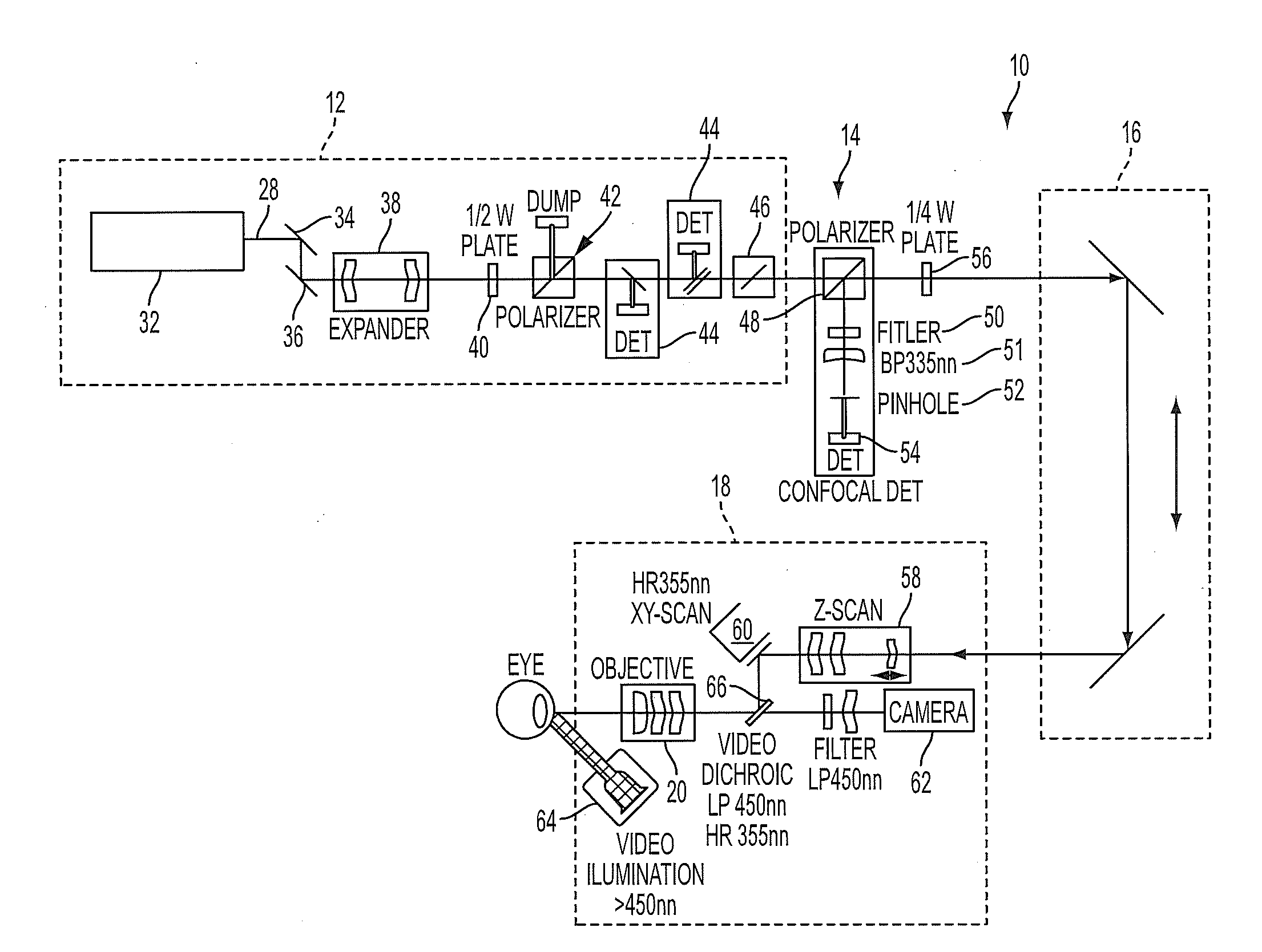
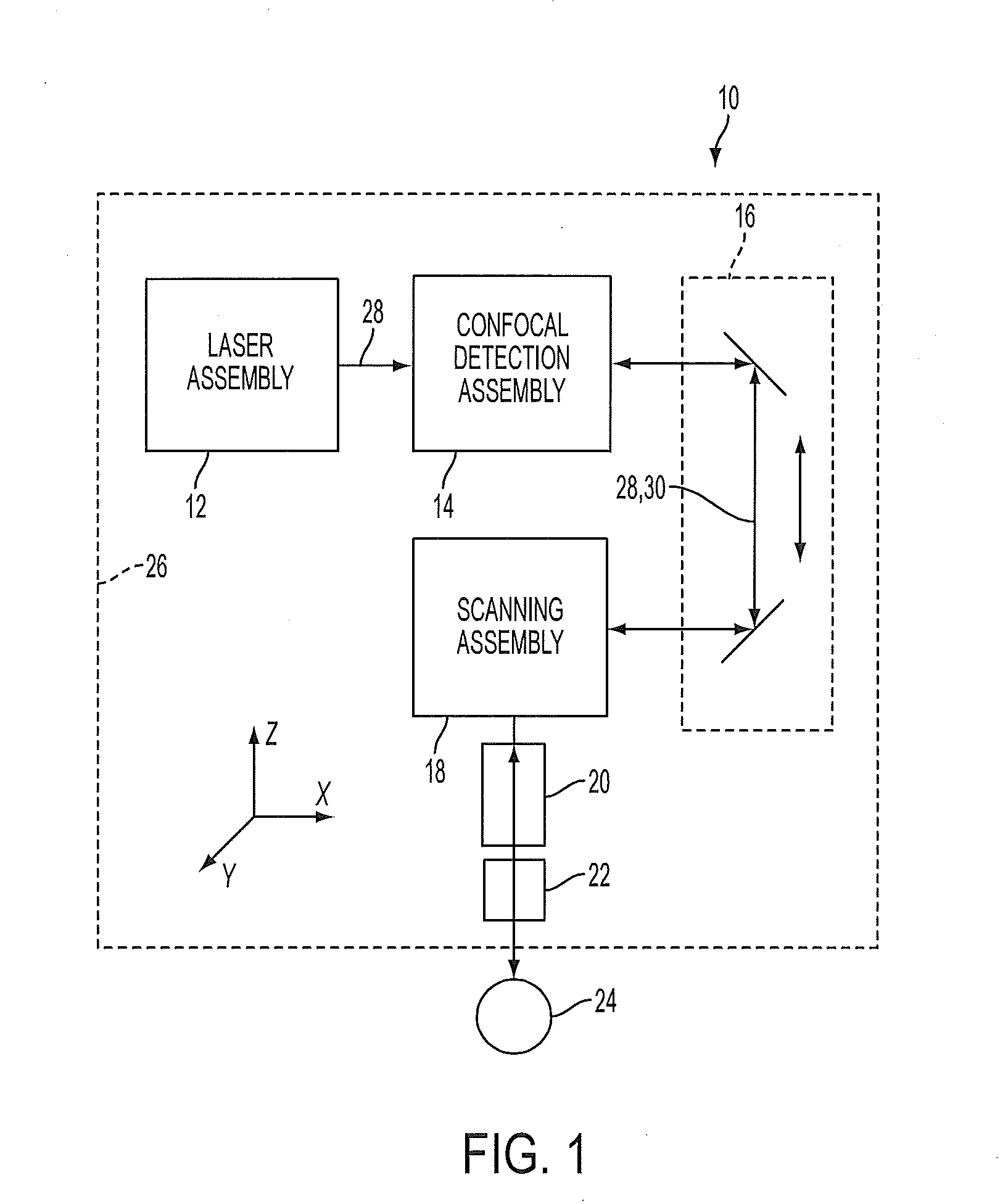
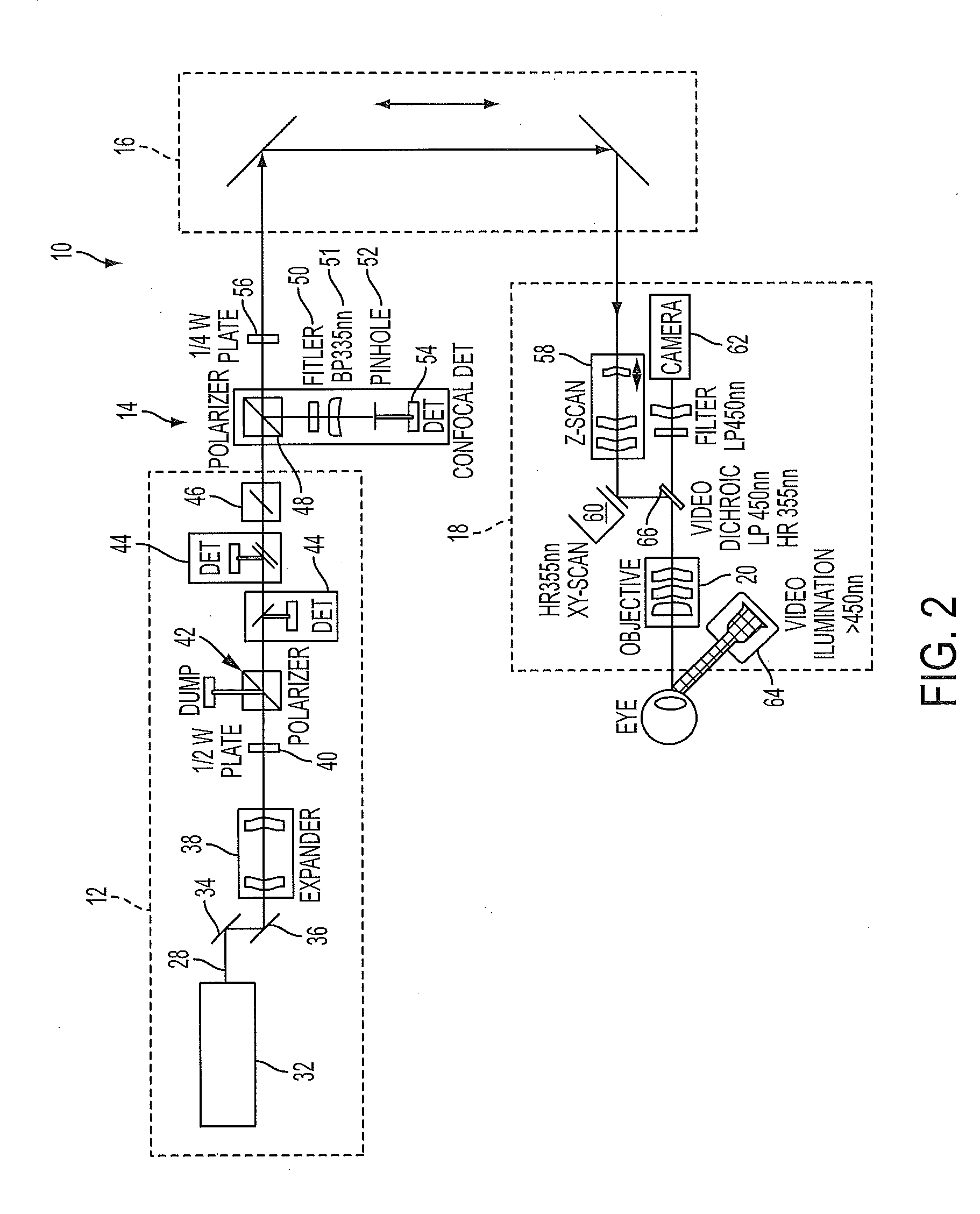
[0078]The following description describes various embodiments of the present invention. For purposes of explanation, specific configurations and details are set forth so as to provide a thorough understanding of the embodiments. It will also, however, be apparent to one skilled in the art that embodiments of the present invention can be practiced without certain specific details. Further, to avoid obscuring the embodiment being described, various well-known features may be omitted or simplified in the description.

[0079]As used herein, the terms anterior and posterior refers to known orientations with respect to the patient. Depending on the orientation of the patient for surgery, the terms anterior and posterior may be similar to the terms upper and lower, respectively, such as when the patient is placed in a supine position on a bed. The terms distal and anterior may refer to an orientation of a structure from the perspective of the user, such that the terms proximal and distal may...


PUM


Abstract

A laser surgery system includes a light source, an eye interface device, a scanning assembly, a confocal detection assembly and preferably a confocal bypass assembly. The light source generates an electromagnetic beam. The scanning assembly scans a focal point of the electromagnetic beam to different locations within the eye. An optical path propagates the electromagnetic beam from a light source to the focal point, and also propagates a portion of the electromagnetic beam reflected from the focal point location back along at least a portion of the optical path. The optical path includes an optical element associated with a confocal detection assembly that diverts a portion of the reflected electromagnetic radiation to a sensor. The sensor generates an intensity signal indicative of intensity the electromagnetic beam reflected from the focal point location. The confocal bypass assembly reversibly diverts the electromagnetic beam along a diversion optical path around the optical element.

Description

CROSS-REFERENCES TO RELATED APPLICATIONS[0001]This application claims priority to and incorporates by reference the entire contents of U.S. Provisional Application No. 61 / 970,854, filed on Mar. 26, 2014, and U.S. Provisional Application No. 62 / 043,749, filed on Aug. 29, 2014.FIELD OF THE INVENTION[0002]The field of the present invention generally relates to laser surgery systems, and more particularly, to systems and methods for imaging and treating the eye.BACKGROUND OF THE INVENTION[0003]Many patients may have visual errors associated with the refractive properties of the eye such as nearsightedness, farsightedness and astigmatism. Astigmatism may occur when the corneal curvature is unequal in two or more directions. Nearsightedness can occur when light focuses before the retina, and farsightedness can occur with light refracted to a focus behind the retina.[0004]There are numerous prior surgical approaches for reshaping the cornea. Over the years, surgical laser systems have repl...

Claims


Application Information

Patent Timeline
Patent Type & Authority Applications(United States)
IPC IPC(8): A61F9/008A61B3/117A61B3/10A61B3/14A61B3/00
CPCA61F9/00825A61B3/14A61B3/0025A61F2009/00897A61B3/1173A61F2009/00844A61B3/1025A61F9/00754A61F9/008A61F2009/00878
Inventor SCHUELE, GEORGBAREKET, NOAHDEWEY, DAVIDHART, JOHN S.GONZALEZ, JAVIER G.WOO, RAYMONDTEISSEYRE, THOMAS Z.GOLDA, JEFFREY A.SHEEHY, KATRINA B.O'MEARA, MADELEINE C.WOODLEY, BRUCE
Owner AMO DEVMENT
Learn More