Control apparatus

a control apparatus and control technology, applied in the direction of electrical control, process and machine control, instruments, etc., can solve problems such as error calculation, and achieve the effect of high control accuracy

Active Publication Date: 2015-10-01
HONDA MOTOR CO LTD
View PDF30 Cites 11 Cited by
  • Summary
  • Abstract
  • Description
  • Claims
  • Application Information

AI Technical Summary

Benefits of technology

[0014]It is an object of the present invention to provide a control apparatus that controls the controlled variable of a controlled object having a response lag characteristic by a combination of a feedforward control method, a response-specifying control method, and a disturbance compensation method, and is capable of ensuring high control accuracy.

Problems solved by technology

Further, the error is calculated using the first input value and the controlled variable.

Method used


Image

  • Control apparatus
  • Control apparatus
  • Control apparatus

Examples


first embodiment

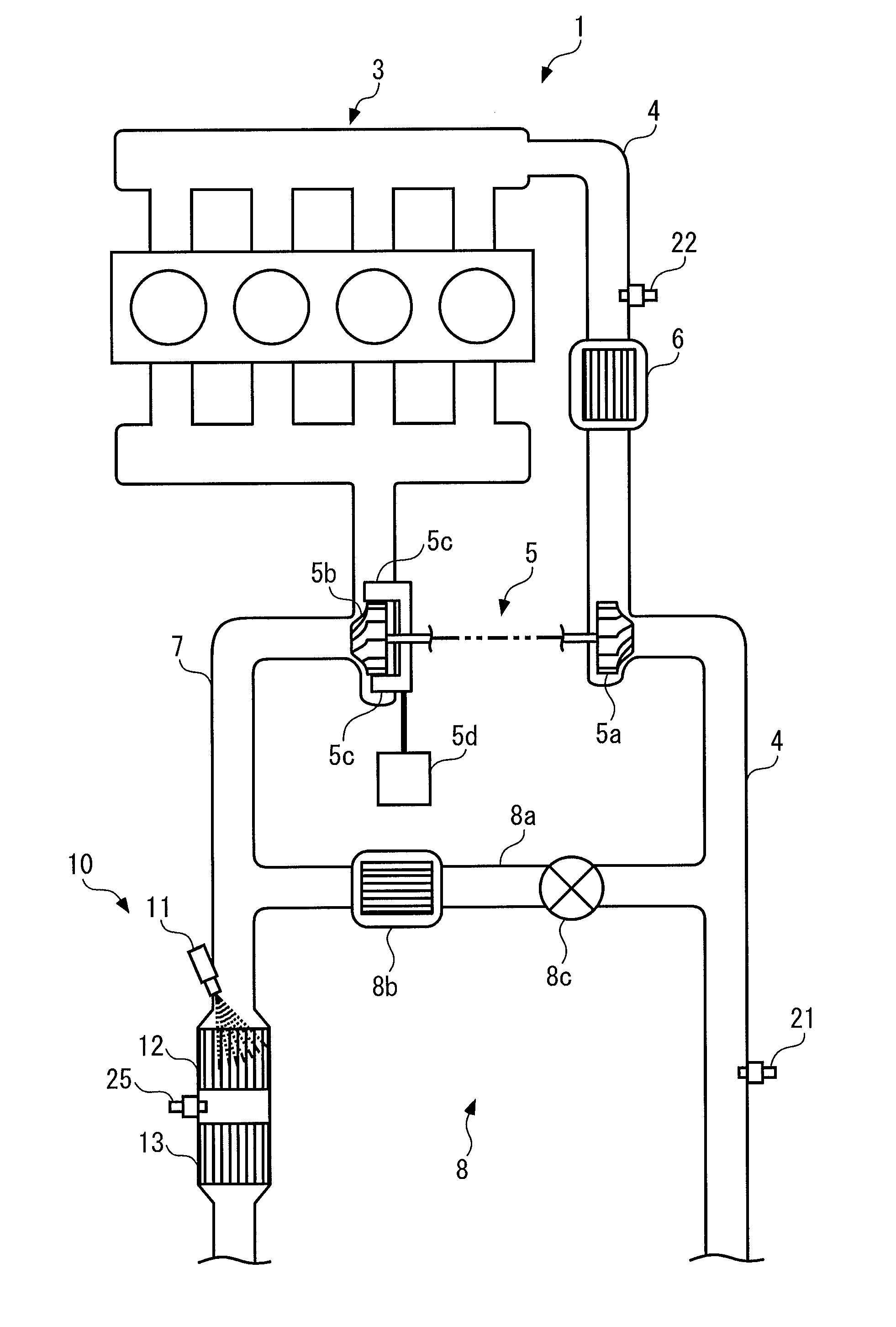
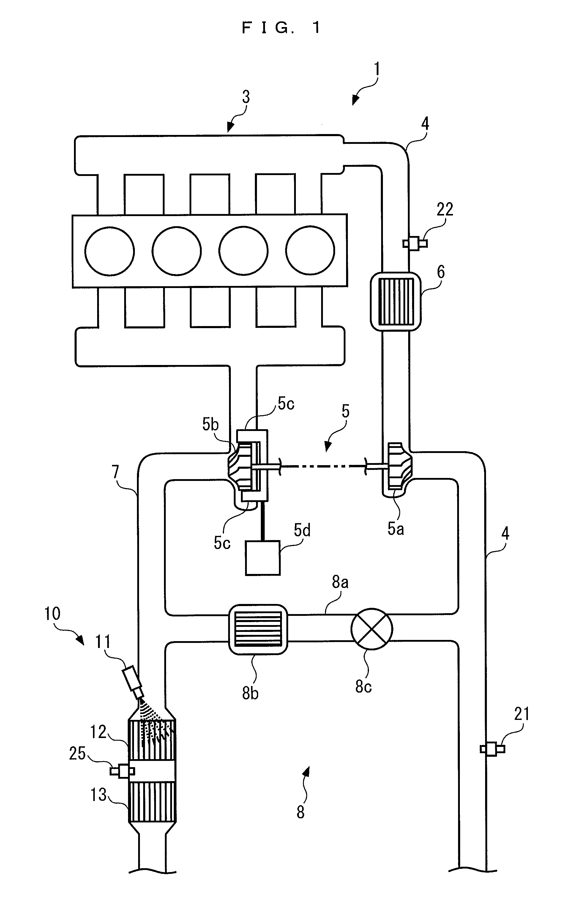
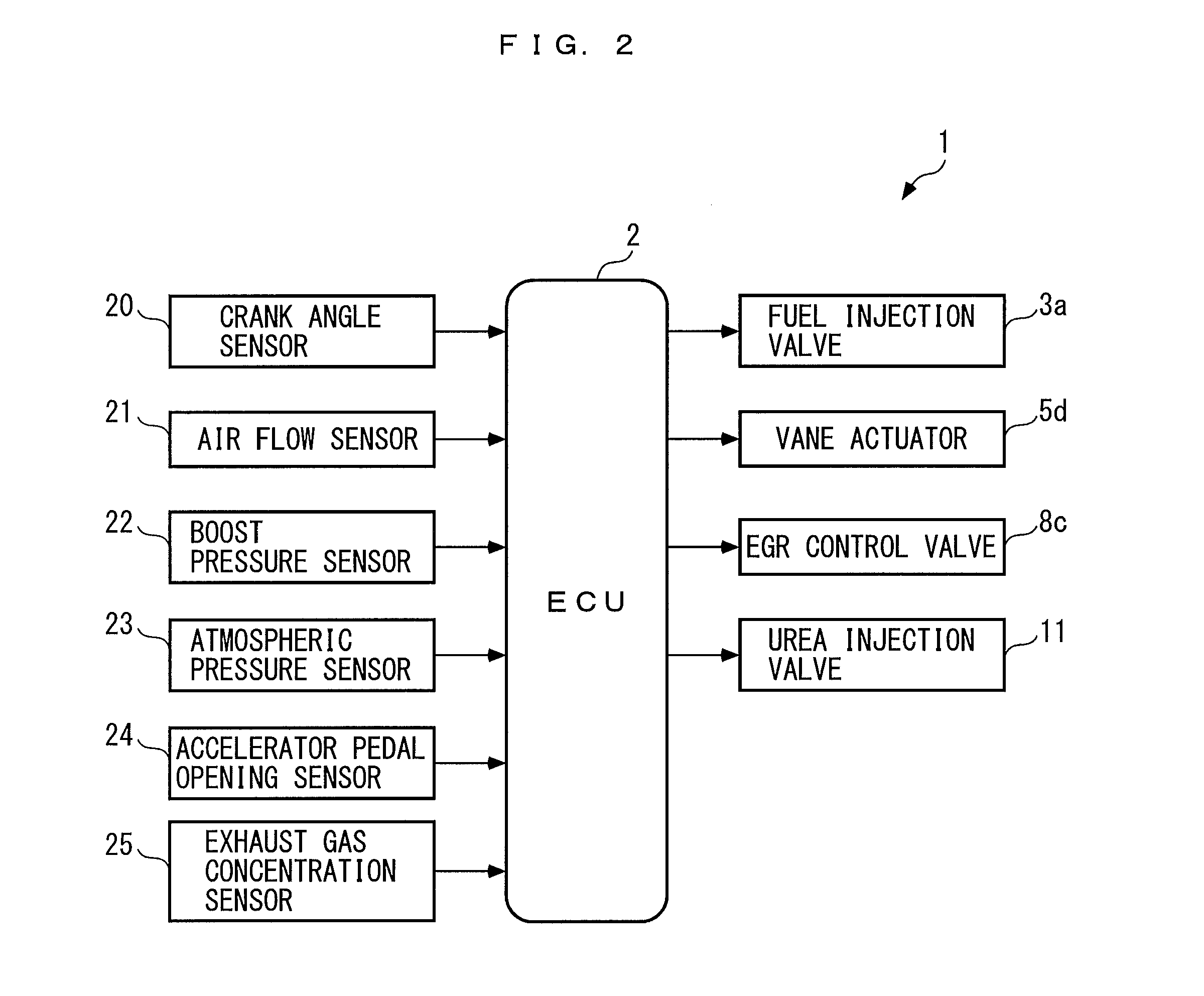
[0043]Hereafter, a control apparatus according to the present invention will be described with reference to the drawings. As shown in FIG. 1, an internal combustion engine (hereinafter referred to as “the engine”) 3 is provided with a supercharger 5 as a controlled object, and the control apparatus 1 of the present embodiment controls boost pressure, that is, performs supercharge control, by controlling the supercharger 5. The control apparatus 1 includes an ECU 2, as shown in FIG. 2, and the ECU 2 performs a supercharge control process as will be described hereinafter.

[0044]The engine 3 is of a four-cylinder diesel engine type, and is installed on a vehicle, not shown, as a motive power source. The engine 3 includes fuel injection valves 3a (only one of which is shown in FIG. 2) provided for respective cylinders, and each fuel injection valve 3a is electrically connected to the ECU 2. A fuel injection amount and fuel injection timing of the fuel injection valve 3a are controlled by...

second embodiment

[0159]Although in the second embodiment, the EGR amount EGRest is used as a controlled variable, instead of this, the EGR rate may be used as a controlled variable.

[0160]Next, a description will be given of a control apparatus 1B according to a third embodiment of the present invention with reference to FIG. 14. The control apparatus 1B according to the present embodiment controls the NH3 slip amount NH3act as a controlled variable by a demanded NH3 slip amount NH3rqr as a control input, by a method similar to the method employed in the control apparatus 1 according to the first embodiment. The control apparatus 1B according to the present embodiment has the same electrical and mechanical arrangements as those of the control apparatus 1 according to the first embodiment, except part of them, so that hereinafter the same components as those of the first embodiment are denoted by the same reference numerals and description thereof is omitted.

[0161]The control apparatus 1B calculates t...

third embodiment

[0179]Although in the third embodiment, the NH3 slip amount NH3act is used as a controlled variable, by way of example, instead of this, the concentration of ammonia that passes through the selective reduction catalyst 12 may be used as a controlled variable.

[0180]Further, although in the first to third embodiments described above, the control apparatus according to the present invention is applied to the supercharger 5, the EGR device 8, and the urea SCR system 10 in the engine 3 for automotive vehicles, by way of example, the control apparatus according to the present invention is not limited to this, but may be applied to any other suitable controlled object that has a response lag characteristic. For example, the control apparatus according to the present invention may be applied to a supercharger in the engine for ships, and may be also applied to a plant system such as petroleum plant and water treatment plant, and industrial equipment that has an oil pressure-based drive syst...


PUM


Abstract

A control apparatus controlling a controlled variable of a controlled object having a response lag characteristic using a combination of feedforward control method, response-specifying control method, and disturbance compensation method. An ECU of the apparatus calculates driver demand boost pressure for feedforward-controlling actual boost pressure as controlled variable, and calculates FB target pressure as value on which response lag characteristic of the actual value to the driver demand value is reflected. The ECU calculates error as difference between the actual and target values, and feedback correction term as sum of equivalent control input including disturbance estimated value and the error as variables and reaching law input, using equation defining relationship between the error, feedback correction term value, and disturbance estimated value, and response-specifying control algorithm, and then adds the correction term value to the driver demand value to thereby calculate demanded boost pressure as control input.

Description

BACKGROUND OF THE INVENTION[0001]1. Field of the Invention[0002]The present invention relates to a control apparatus for controlling a controlled object having a response lag characteristic.[0003]2. Description of the Related Art[0004]Conventionally, as a control apparatus, there has been known one disclosed in Japanese Laid-Open Patent Publication (Kokai) No. 2005-171893. This control apparatus controls a variable nozzle type turbocharger as a controlled object. This control apparatus calculates a target boost pressure epimtrg according to operating conditions of the engine, and feedback-controls an actual boost pressure epim such that the actual boost pressure epim becomes equal to the target boost pressure epimtrg, using a feedback control algorithm.[0005]With this feedback control algorithm, a boost pressure difference epimdlt, which is a difference between the actual boost pressure epim and the target boost pressure epimtrg, is calculated, and a feedback control term epvnpmfb i...

Claims


Application Information

Patent Timeline
Patent Type & Authority Applications(United States)
IPC IPC(8): F01N3/20F02D41/14F02D41/00
CPCF01N3/208F02D41/0052F02D41/0007F02D41/1401F01N2900/0408F02D2041/1431F01N2610/02F01N2900/1818F02D41/0077F02B37/24F02D41/10F02D2041/1409F02D2041/1422Y02T10/12Y02T10/40
Inventor YASUI, YUJI
Owner HONDA MOTOR CO LTD
Why Eureka
Try Eureka