Check patentability & draft patents in minutes with Patsnap Eureka AI!

Method and apparatus for data capture in DDR memory interface

a technology of ddr memory interface and data acquisition, applied in the direction of information storage, static storage, digital storage, etc., can solve the problems of difficult to capture the correct data signal, substantial jitters and/or on-chip variations, and undesirable effects, so as to reduce the circuit area and/or power

Active Publication Date: 2015-10-01
MEGACHIPS
View PDF2 Cites 2 Cited by
  • Summary
  • Abstract
  • Description
  • Claims
  • Application Information

AI Technical Summary

Benefits of technology

The present patent provides a method and device for data acquisition in a memory system. It addresses issues like duty distortion and jitter while reducing circuit area and power consumption. The technical effects of this patent include improved data reading performance from aDDR memory and reduced impact on signal quality.

Problems solved by technology

However, the use of such a DLL not only requires additional hardware (such as FIFO circuitry), but also, causes substantial jitters and / or on-chip variations.
The use of such a DLL makes it difficult to capture the correct data signal and, thus, is not desirable.
However, these patents do not solve the problem of capturing the DQ in the READ mode where the DQS is not aligned at the center of the DQ.
However, synchronizing DQ with the DQS requires separating rising and falling edges of the DQS, which requires additional circuitry and logic implementation.
Such a data capturing scheme is not suitable for a DDR system because it requires ‘k’ number of multiphase clock generating circuits for a k-bit word length memory.
Such a scheme not only adds to the circuit area, but also, consumes a lot of power.
However, the use of this voting scheme also consumes a lot of power and requires a large area on the circuit.
Therefore, even upon implementing such a scheme for data capturing, there still remains an unfulfilled need of capturing correct data with reduced circuitry, power consumption, and area requirements.

Method used


Image

  • Method and apparatus for data capture in DDR memory interface
  • Method and apparatus for data capture in DDR memory interface
  • Method and apparatus for data capture in DDR memory interface

Examples


Embodiment Construction

[0035]The present disclosure relates to a unique technique of reading of data (DQ) bits in a memory system by an SDRAM controller from a memory, such as a DDR memory that avoids jitters and on-chip variations, which, in turn, reduces the timing margins. According to one or more embodiments described hereinafter, the DDR memory and the SDRAM controller, along with SDRAM PHY have been described as independent devices in the memory system; however, one of ordinary skill in the art would appreciate that they may be on a single chip or on a plurality of independent chips that are interfaced together to communicate with one another. Further, while the embodiments of the disclosure hereinafter are shown for DDR memory systems, the same is not limited to the described embodiments and could be equally applied to any other single or multi-chip memory systems.

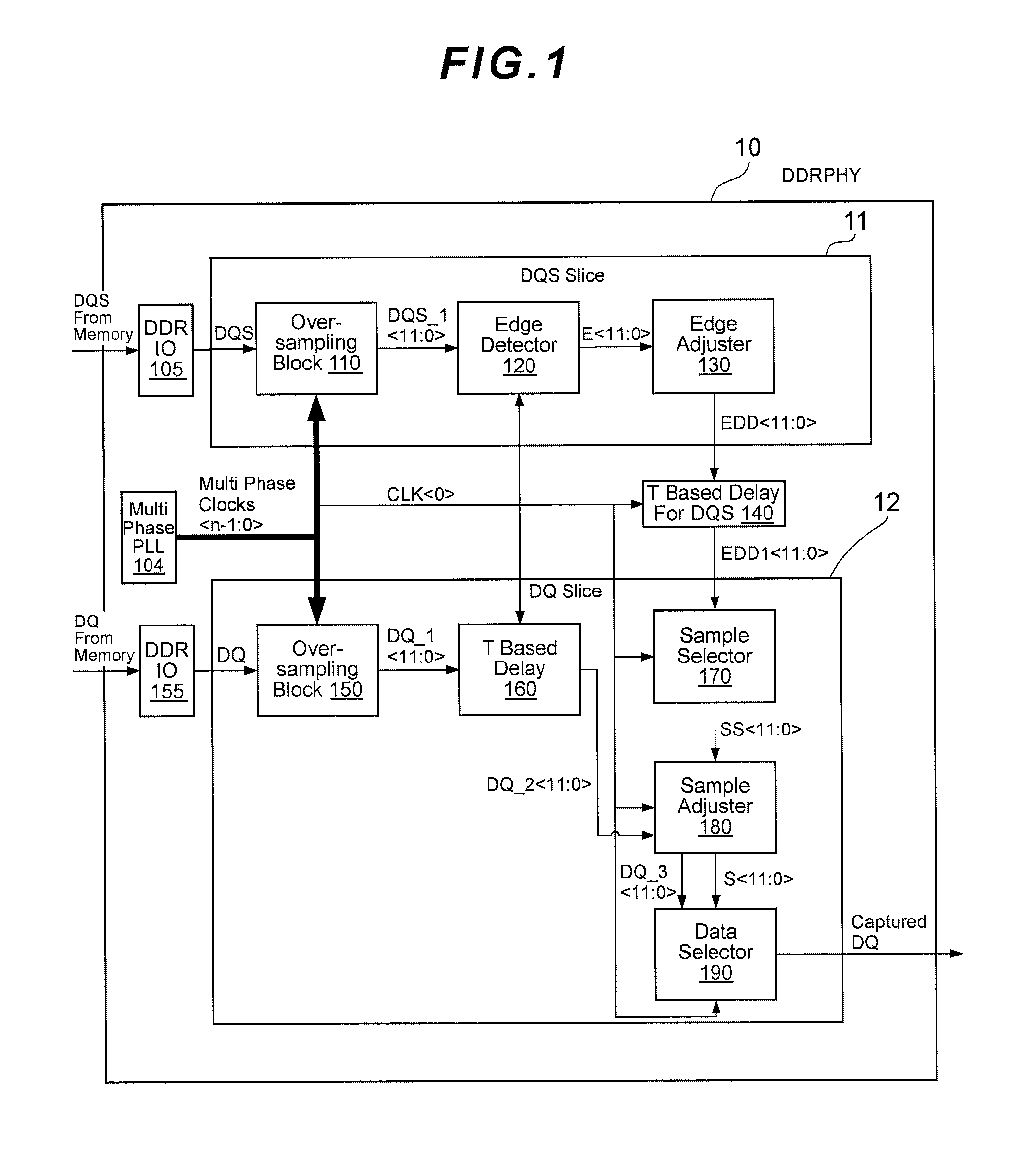
[0036]FIG. 1 is a functional block diagram of a DDR PHY 10 of the memory system (not shown in its entirety) according to one or more emb...


PUM


Abstract

A method for data acquisition in a memory system includes oversampling a data signal and a strobe signal with a multiphase clock having n phases to generate a series of data signals and a series of strobe signals representing a first data series and a first strobe series respectively, generating a second strobe series by edge detection of the first strobe series followed by retiming of the edge detected series, generating a third strobe series by edge adjustment of the second strobe series, wherein the edge adjustment ensures that there are no overlapping edges among the signals of the third strobe series, generating a sample selected series by linear shifting of each signal of the third strobe series by n / 2, generating a second data series by retiming the first data series, generating a third data series by sample adjustment of the second data series, wherein the sample adjustment ensures that the third data series is in synchronization with a sampling window of the sample selected series, and determining a final data signal by multiplexing the third data series with the sample selected series.

Description

FIELD OF THE INVENTION[0001]The present disclosure generally relates to a method and apparatus for data acquisition in an electronic system. More particularly, the present disclosure relates to reading of data (DQ) bits, from a Double Data Rate (DDR) memory in a DDR memory interface, and specifically by a PHY (physical interface) thereof.BACKGROUND OF THE INVENTION[0002]Digital electronics systems and computer systems generally employ a memory subsystem that includes memory devices interfaced to one or more processors / controllers that perform read-write function on the memory devices. Because the speed of operation of processors / controllers is higher than that of the memory subsystem, the operation speeds of such a memory subsystem can always be improved so as to enhance the overall performance of the system.[0003]One of the approaches for improving performance is the use of DDR SDRAM memory devices. The DDR SDRAM enables data to be read and written on both rising and falling edges ...

Claims


Application Information

Patent Timeline
Patent Type & Authority Applications(United States)
IPC IPC(8): G11C11/4076G11C11/409
CPCG11C11/409G11C11/4076G11C7/22G11C7/222G11C11/4093G11C11/4096
Inventor SARRAJU, DINAKAR VENKATARAMAKRISHNA, PURUSHOTHAM BRAHMAVAR
Owner MEGACHIPS
Features
  • R&D
  • Intellectual Property
  • Life Sciences
  • Materials
  • Tech Scout
  • Unparalleled Data Quality
  • Higher Quality Content
  • 60% Fewer Hallucinations
Learn More