
Methods for turbocharged engine with cylinder deactivation and variable valve timing

a technology of variable valve timing and cylinder deactivation, which is applied in the direction of machines/engines, output power, electric control, etc., can solve the problems of increasing load, increasing the cost of variable valve drive, and affecting the efficiency of the engine, so as to reduce the fuel consumption of the internal combustion engine and increase the overall efficiency

Active Publication Date: 2015-10-08
FORD GLOBAL TECH LLC
View PDF5 Cites 2 Cited by
  • Summary
  • Abstract
  • Description
  • Claims
  • Application Information

AI Technical Summary

Benefits of technology

The patent text describes a technical solution to improve the efficiency of a multi-cylinder engine. It includes a bypass line and a shut-off element that prevents the compressor of a second exhaust-gas turbocharger from interfering with the operation of the first compressor during partial deactivation. The bypass line also serves as a safety measure to prevent delivery action against the shut-off element when the overall intake line is closed. The remaining cylinders, which remain in operation during the partial deactivation, have better mixture formation due to the increased air mass or mixture mass supplied. This results in improved engine efficiency as deactivated cylinders do not generate any wall heat losses.

Problems solved by technology

Fuel consumption and thus efficiency pose a problem in particular in the case of Otto-cycle engines, or applied-ignition internal combustion engines.
However, these parameters have an influence on the combustion process, and thus on fuel consumption, and can be varied to a greater or lesser extent by using variable valve drives.
Variable valve drives are however expensive.
However, because in the case of constant engine power the deactivation of at least one cylinder of a multi-cylinder internal combustion engine increases the load on the other cylinders that are still operational, such that said cylinders operate in regions of higher loads, in which the specific fuel consumption is lower.

Method used


Image

  • Methods for turbocharged engine with cylinder deactivation and variable valve timing
  • Methods for turbocharged engine with cylinder deactivation and variable valve timing
  • Methods for turbocharged engine with cylinder deactivation and variable valve timing

Examples


Embodiment Construction

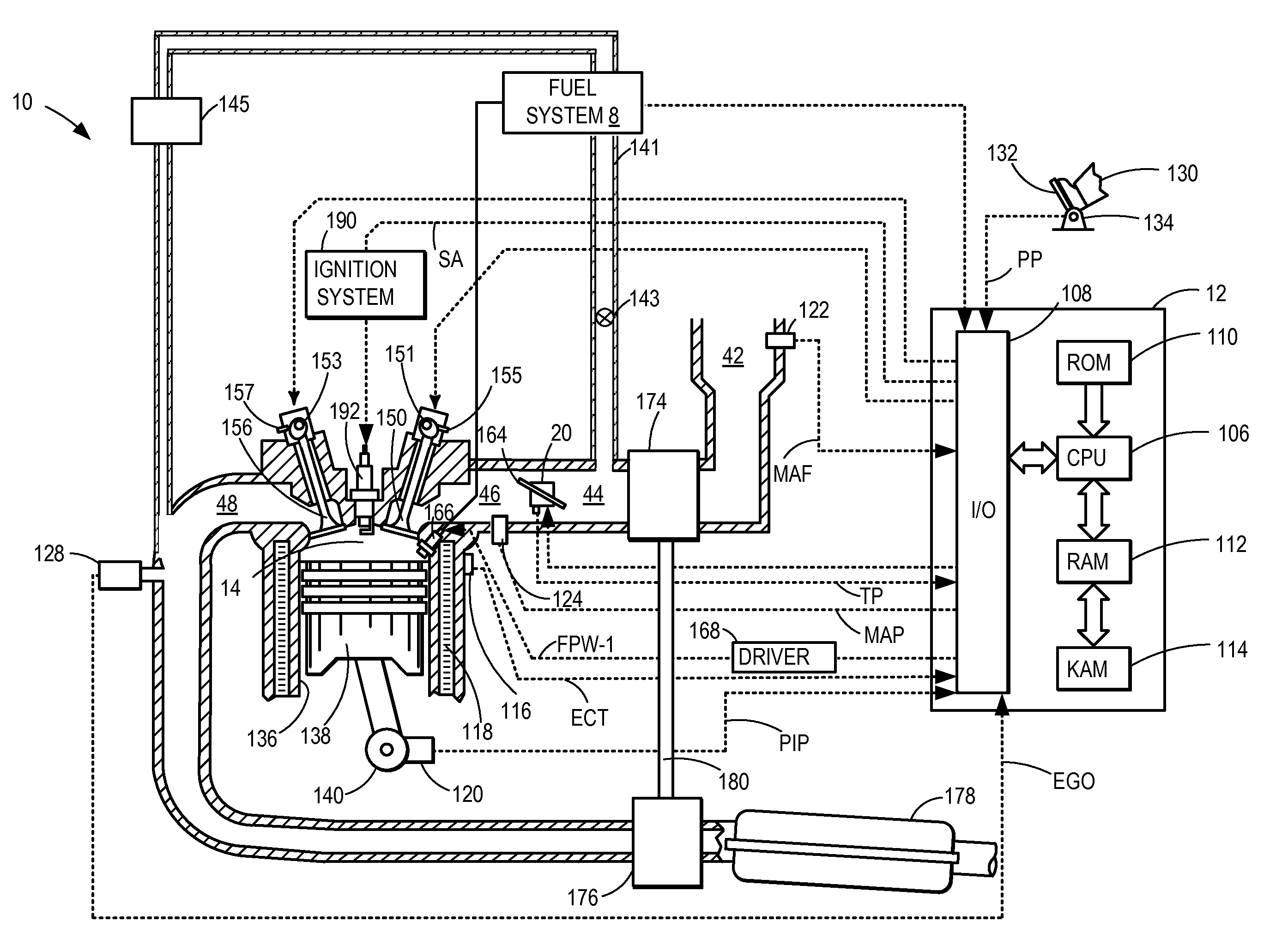
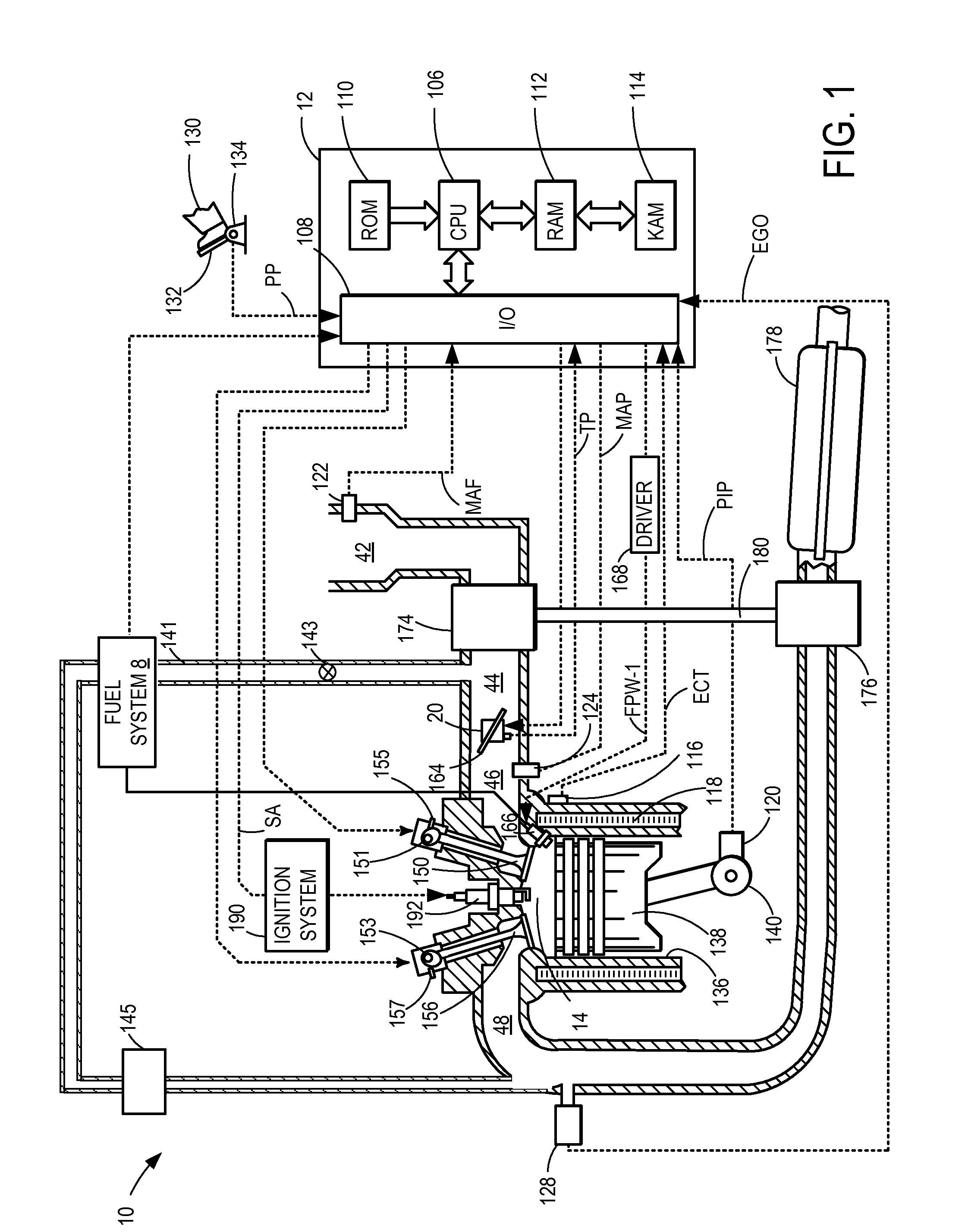
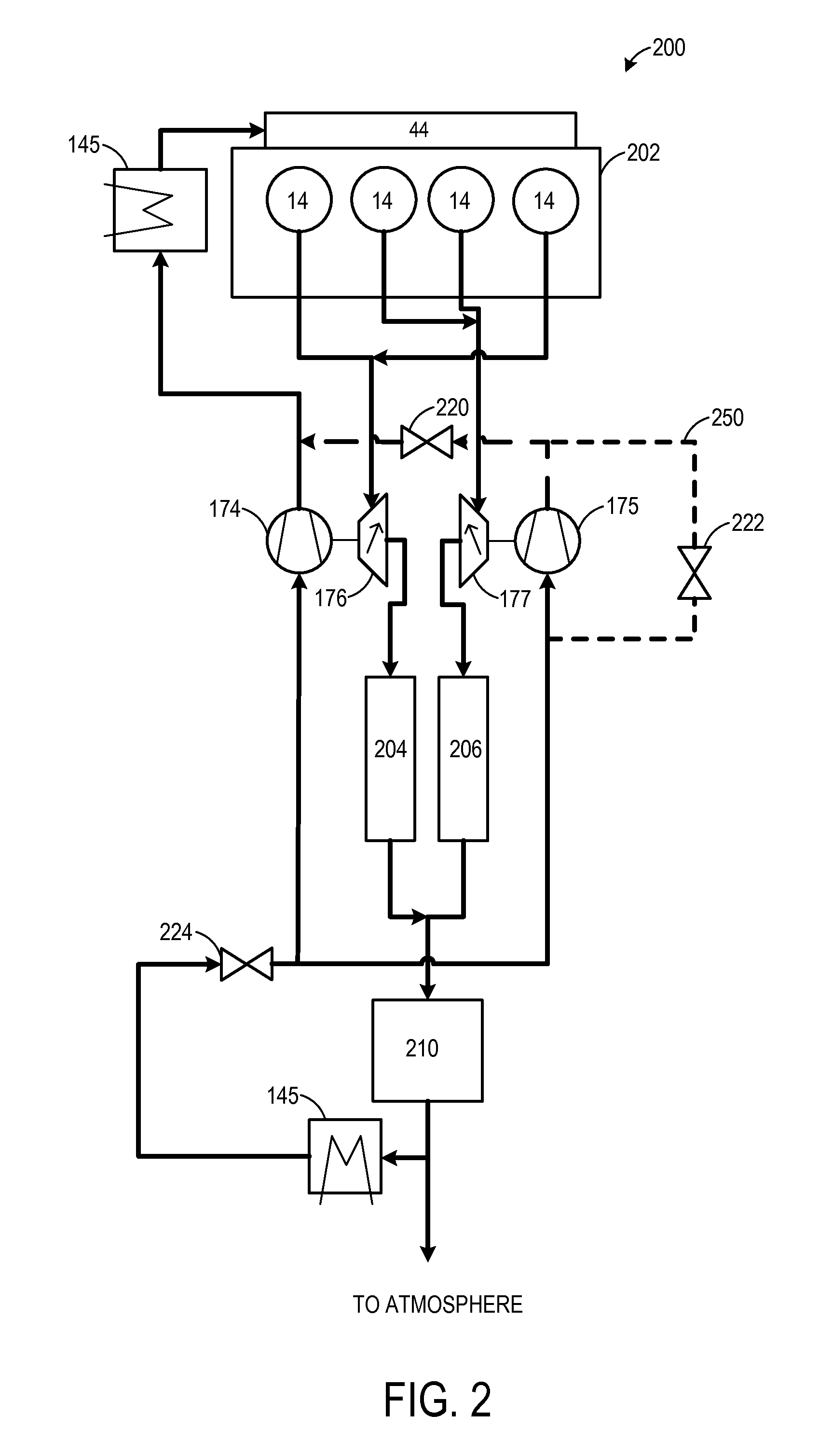
[0014]The present disclosure relates to a system and methods for operating a supercharged auto-ignition internal combustion engine having at least two cylinders and having at least one at least partially variable valve drive. For this reason, FIG. 1 shows an example embodiment of an engine according to the present disclosure. FIG. 2 further shows an exemplary four cylinder engine to depict possible airflow pathways within the system. FIG. 3 schematically shows the characteristic map of a first embodiment of the supercharged auto-ignition internal combustion engine while FIG. 4 is included to illustrate an exemplary flow chart for switching between operating modes of the engine. FIG. 5 is included to provide a simulated operating sequence according to the method of FIG. 4.

[0015]The present disclosure further relates to a method for operating a supercharged auto-ignition internal combustion engine having at least two cylinders and having at least one at least partially variable valve ...


PUM


Abstract

A system and methods are described for a turbocharged engine, comprising powering the engine using a first operating cylinder, supplementing the power using a second switchable cylinder, deactivating the second switchable cylinder responsive to a load below a first threshold, and closing a first shut-off element downstream of a compressor during the partial deactivation to prevent a first turbocharger from imparting a delivery action into a second compressor during the partial deactivation. Embodiments are further described wherein a bypass line in a second exhaust line further serves as a short-circuit line to prevent the second compressor from imparting a delivery action against the closed first shut-off element. A variable valve timing is then included to further optimize the combustion process during the partial deactivation.

Description

CROSS REFERENCE TO RELATED APPLICATIONS[0001]The present application claims priority to German Patent Application No. 102014206510.0, filed Apr. 4, 2014, the entire contents of which are hereby incorporated by reference for all purposes.FIELD[0002]The present description relates to methods for operating a supercharged engine having at least two cylinders and a partially variable valve drive.BACKGROUND AND SUMMARY[0003]Reducing fuel consumption of an internal combustion engine is one means to increase overall efficiency. Fuel consumption and thus efficiency pose a problem in particular in the case of Otto-cycle engines, or applied-ignition internal combustion engines. One option for optimizing the combustion process includes using a partially variable valve drive, perhaps in combination with direct fuel injection.[0004]Valve drives are known in which both the lift of the valves and also the control timing are invariable. However, these parameters have an influence on the combustion p...

Claims


Application Information

Patent Timeline
IPC IPC(8): F02D17/02F02B37/007F02D13/02F02B37/22F02D41/00
CPCF02D17/02F02B37/22F02D41/0007F02D2041/0012F02D41/005F02D13/0265F02B37/007F02D13/0261F02B25/145F02B37/001F02B37/002F02D13/0207F02D13/0219F02D13/06F02D41/0087F02M26/01F02M26/08Y02T10/12Y02T10/40
Inventor KEMMERLING, JOERGSOMMERHOFF, FRANZ ARNDKUSKE, ANDREASSMILJANOVSKI, VANCOKINDL, HELMUT MATTHIASWILLEMS, WERNERHERUDEK, CLAUDIA KATHARINAFORSTING, MICHAELVAN DEN HEUVEL, BAS LAMBERTUSHEMINK, WILBERTCONEE, CLAUDIAFRITSCHE, RICHARD
Owner FORD GLOBAL TECH LLC
Learn More