
Method and Apparatus for Thermally Protecting and/or Transporting Temperature Sensitive Products

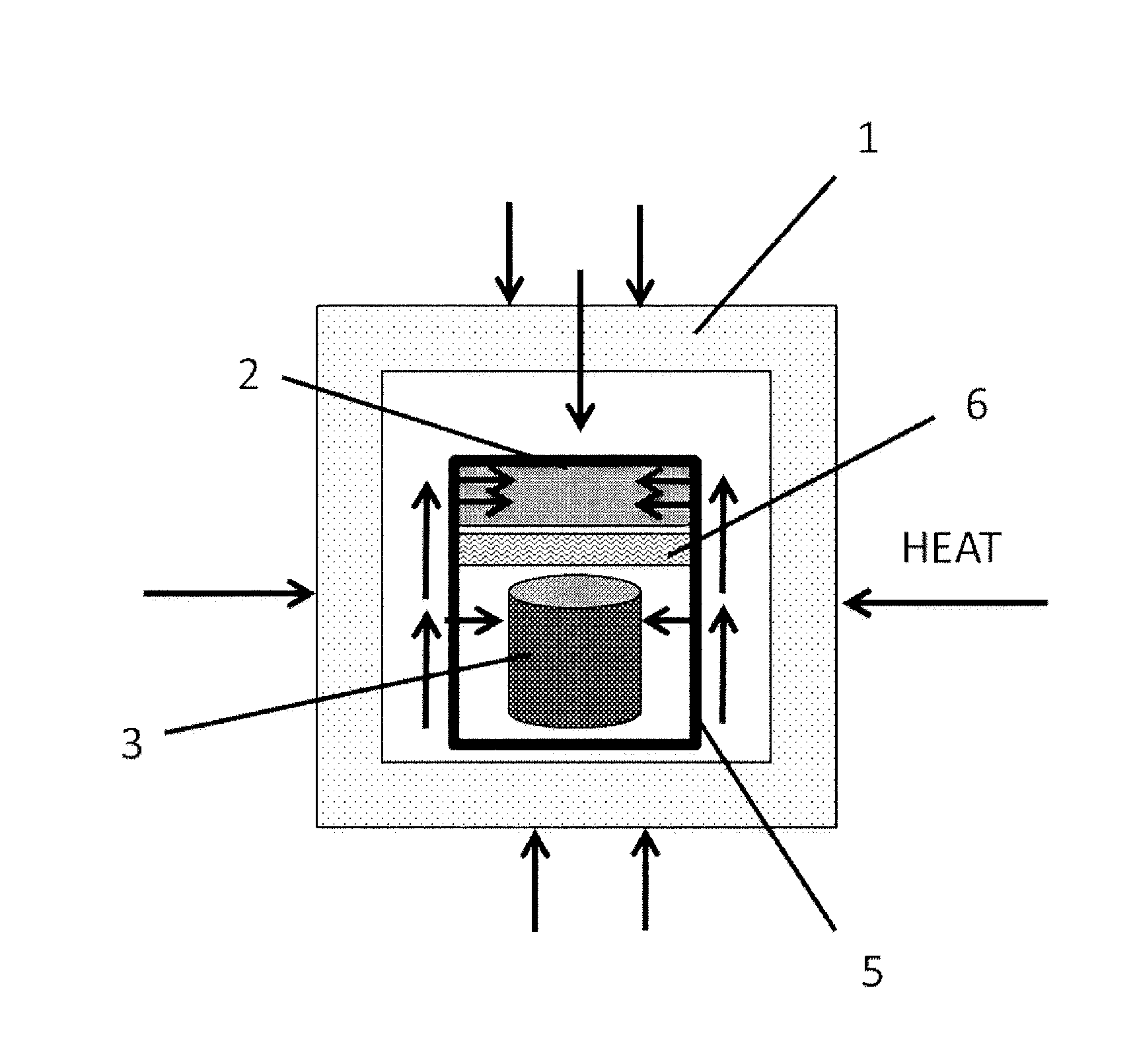
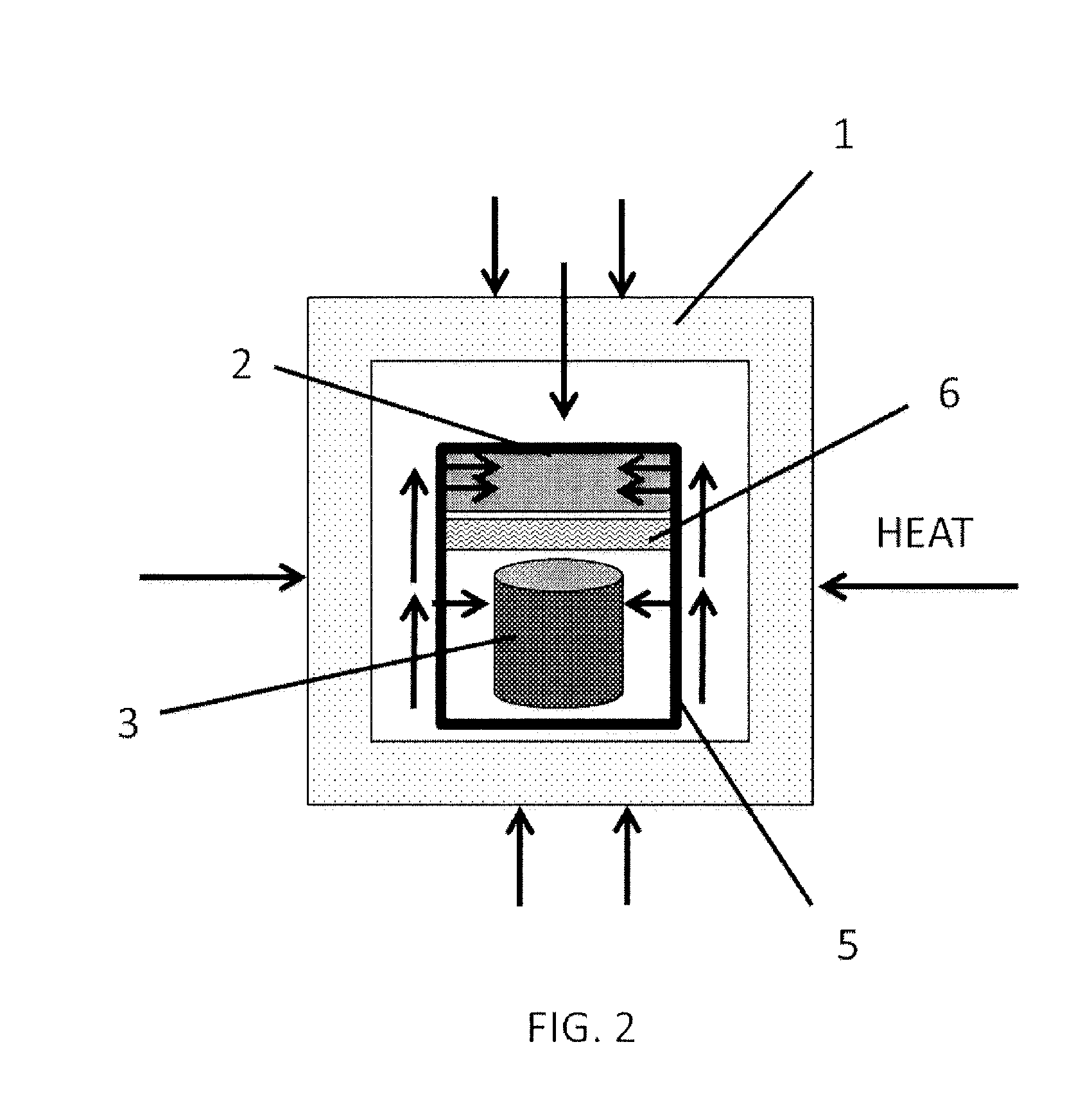
a technology for transporting temperature sensitive products and controlling the thermal environment of payloads, which is applied in the direction of domestic cooling apparatus, lighting and heating apparatus, packaging, etc., can solve the problems of if effective at all, and reducing the effect of natural convection

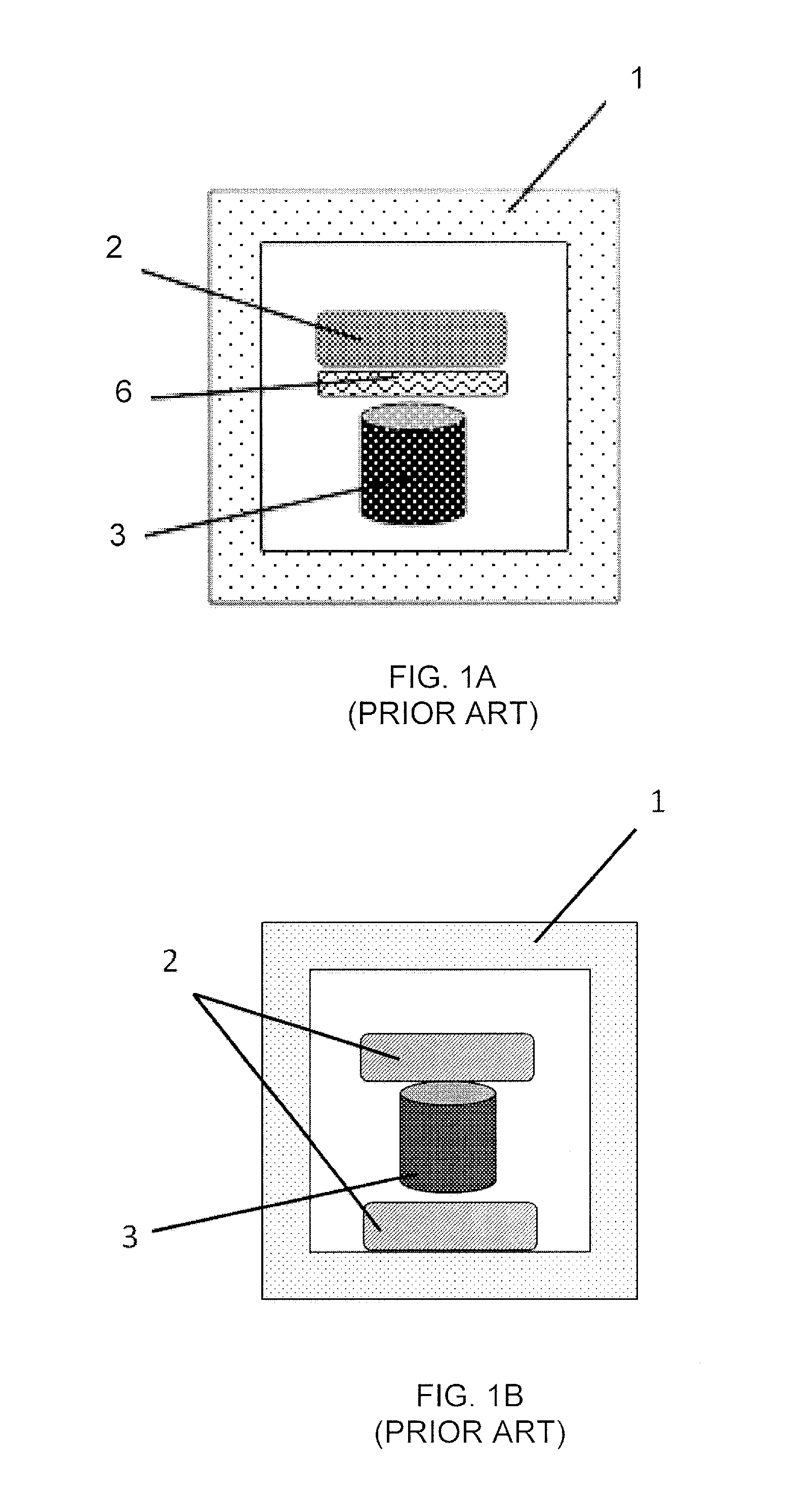
Active Publication Date: 2015-10-08
ILLUMINATE CONSULTING
View PDF0 Cites 9 Cited by
  • Summary
  • Abstract
  • Description
  • Claims
  • Application Information

AI Technical Summary

Benefits of technology

This approach extends the time products remain within a desired temperature range and reduces exposure to undesirable temperatures, enhancing thermal protection and reducing shipping costs by improving temperature maintenance performance.

Problems solved by technology

A disadvantage of using natural convection to transfer the heat inside the package is that natural convection is more effective when air gaps exist between the container and the payload in order to allow for the air movement to occur.
However, even when the cold bank is positioned on top of the product when the container is packed, the container is often rotated during shipping, thus making natural convection less effective, if effective at all.
However, the use of filling material can decrease, or eliminate, natural convection, as less free space is available for the air to circulate.

Method used


Image

  • Method and Apparatus for Thermally Protecting and/or Transporting Temperature Sensitive Products
  • Method and Apparatus for Thermally Protecting and/or Transporting Temperature Sensitive Products
  • Method and Apparatus for Thermally Protecting and/or Transporting Temperature Sensitive Products

Examples


example 1

Optimizing the Use of the Cold Bank

[0064]A 0.028 m3, 25.4 mm thick EPS container with a 0.68 kg ice pack conditioned at −20° C. was used for this test. Three insulated packaging systems were tested using the regular configuration against an embodiment of the invention that involves wrapping the payload and the cold bank (two 10 ml vials, one 0.68 kg ice pack at the top) with an aluminum conductive equalizer sheet of a thickness of 0.016 mm that covered 100% of the surface area of the payload and one with an aluminum conductive equalizer sheet with a thickness of 0.016 mm that covered 30% of the surface area of the payload. Reducing the surface area can also play an important role in the thermal efficiency of the conductive material covering system. As it can be seen in Table 4 below, a conventional insulated container using a cold bank at the top can be improved by using a 30% total surface aluminum conductive equalizer sheet but be further optimized with a more significant gain by...

example 2

Reducing the Temperature Differences Inside the Load

[0066]Insulated container: EPS 38 mm wall with outside dimensions 292 mm×228 mm×336 mm

Load: 127 mm×178 mm×203 mm (with 7 prefilled syringes (2 ml each) and 4 vials (5 ml each)) conditioned at 24° C.

Cold bank: 0.45 kg ice pack (2) conditioned at −20° C. placed on the top

Conductive equalizer system: 127 mm×178 mm×203 mm (outside layer like a box)

Conductive equalizer materials:

[0067]A. LDPE film 0.05 mm thickness (thermal conductivity: 0.33 W / (m-K)

[0068]B. Mylar reflective film 0.05 mm thickness (thermal conductivity: 0.15 W / (m-K)

[0069]C. Aluminum sheet 0.016 mm thickness (thermal conductivity: 205 W / (m-K)

[0070]D. Aluminum sheet 0.3 mm thickness (thermal conductivity: 205 W / (m-K)

[0071]E. Steel sheet 0.3 mm thickness (thermal conductivity: 43 W / (m-K)

[0072]F. Copper sheet 0.3 mm thickness (thermal conductivity: 401 W / (m-K)

Filling material in free space: bubble wrap LDPE (FIG. 8)

Results:

[0073]

Temperature (° C.) at locations 1 and 2 after...

example 3

Reducing the Temperature Differences Inside the Load

[0076]Insulated container: EPS 25.4 mm wall with outside dimensions 203 mm×203 mm×203 mm

Load: 152 mm×152 mm×76 mm (4 vials (5 ml each)) conditioned at 24° C.

Cold bank: 0.45 kg ice pack conditioned at −20° C. placed on the top

Conductive equalizer system: 152 mm×152 mm×76 mm (outside layer like a box) Conductive equalizer materials:

[0077]A. LDPE film 0.05 mm thickness (thermal conductivity: 0.33 W / (m·K)

[0078]B. Aluminum sheet 0.3 mm thickness (thermal conductivity: 205 W / (m·K)

[0079]C. Copper sheet 0.3 mm thickness (thermal conductivity: 401 W / (m·K)

Filling material in free space: bubble wrap LDPE (FIG. 9)

Results:

[0080]

Temperature (° C.) at locations 1 and 2 after 12 hours when exposed to 24° C.Conductive Temperature equalizer typelocation 1location 2differenceA6.310.54.2B7.110.02.9C6.49.92.5

[0081]In a specific embodiment, the cold bank is at least 70 mm away from the furthest point in the payload. In further embodiments, the cold bank...


PUM


Abstract

Embodiments of the subject invention relate to a method and apparatus for thermally protecting a product, such as when storing and / or shipping a product, so as to control the temperatures the products are exposed to. Embodiments can increased the amount of time the product and / or portions of the product experience a desired temperature range and / or reduce the amount of time the product and / or portions of the product experience temperatures outside of the desired temperature range and / or experience an undesirable temperature range. Embodiments can incorporate thermally conductive materials, such as aluminum sheets, positioned around and / or near the product positioned inside a packaging container, such that the conductive materials conduct heat from one or more locations in the interior of the package to one or more other locations in the interior of the package. These thermally conductive materials can be referred to as conductive equalizers. The conductive equalizers can conductively transfer heat from the hotter portions of the interior of the container to cooler portions of the interior of the container and / or from portions of the interior desired to be cooled to the cold bank. Conducting heat from hotter portions to cooler portions, or from portions to be cooled to the cold bank can result in a more uniform temperature distribution around the product.

Description

CROSS-REFERENCE TO RELATED APPLICATIONS[0001]This application is a continuation of PCT / US 2013 / 077600, which claims the benefit of U.S. Provisional Application Ser. No. 61 / 745,620, filed Dec. 23, 2012 and U.S. Provisional Application Ser. No. 61 / 787,205, filed Mar. 15, 2013, the disclosures of which are hereby incorporated by reference in their entirety, including all figures and tables.BACKGROUND OF INVENTION[0002]Embodiments of the subject invention relate to a method and apparatus for controlling a thermal environment of a payload, such as a thermal sensitive product. Embodiments are designed to move heat within an enclosed environment, such as a packaging system for temperature sensitive products, in order to more efficiently use the cold bank (or hot bank) and reduce hot or cold spots inside the packaging system.[0003]The most common packaging systems for transporting temperature sensitive products use an insulated container, such as a Styrofoam container, and a cold bank, such...

Claims


Application Information

Patent Timeline
Patent Type & Authority Applications(United States)
IPC IPC(8): F25D3/06
CPCF25D3/06F28F13/00F25D3/08F28F2013/001F25D2303/0844F25D2303/0845B65D81/3816F25D2303/085F25D2331/804
Inventor EMOND, JEAN-PIERREGERMAIN, MELISSA
Owner ILLUMINATE CONSULTING
Learn More