Multi-frequency array antenna

a multi-frequency array and antenna technology, applied in the field of mobile communication, can solve the problems of not being able to fundamentally solve the arraying problem of existing dual-broad frequency antennas, not being able to achieve the optimal radiation performance of high/low frequency array antennas, and attracting attention from site selection and construction of new stations by operators, etc., to achieve the optimization of the electrical performance of signals in all band ranges, minimizing signal interference, and optimizing the effect of multi-frequency array antenna

Active Publication Date: 2015-10-08
COMBA TELECOM TECH (GUANGZHOU) CO LTD
View PDF2 Cites 17 Cited by
  • Summary
  • Abstract
  • Description
  • Claims
  • Application Information

AI Technical Summary

Benefits of technology

[0018]Compared with the prior art, the technical effect of the present invention is not anticipatable:
[0019]First, in the present invention, with respect to the first distance between the low-frequency radiation units and the second distance between the high-frequency radiation units, an optimal setting is obtained by limiting the first distance to be 2.5 times of the second distance, which substantially arranges the low-frequency radiation column element and the high-frequency radiation column element on the same first reference axis, such that the electrical performance of signals in all band ranges is optimized, consequently it can be simultaneously compatible with mobile communication systems in the range of three operating bands of 2G, 3G and 4G. As a result, signal receiving and transmission can be performed for all of the current mobile communication systems, such as GSM, CDMA and LTE, with one set of multi-frequency array antenna, which solves the difficulty that has not been addressed and has obsesses those skilled in the art for many years.
[0020]Second, by defining that the low-frequency radiation column element employs two types of low-frequency radiation units with different structures, it can effectively avoid the phenomenon that their radiation arms are overlapped when projected orthographically to the orthographical projection plane of the metal reflector, thereby minimizing the signal interference between the low-frequency radiation column element and the high-frequency radiation column element and ensuring that the multiple relationship between the above two distances is more reliable.
[0021]Furthermore, by limiting that the first distance and the second distance are 0.6-1.0 times of their frequency band ranges, preferably 0.8 times, it further optimizes the entire arraying effect such that the electrical performance of the multi-frequency array antenna according to the present invention is optimized.

Problems solved by technology

As people have been paying increasingly high attention to electromagnetic radiation, the site selection and construction of new stations by operators often attract attention from and are resisted by residents living in the neighborhood.
Therefore, the relationship that the distance between low-frequency radiation units is 2 times of the distance between high-frequency units is no longer able to achieve the optimal radiation performance of the high / low frequency array antenna.
Apparently, such an arraying configuration is merely an improvement, which cannot fundamentally solve the arraying problem of existing dual-broad frequency antennas.
According to the array antenna theory, a distance between low-frequency radiation units that exceeds one times of the wavelength apparently has serious impact on the performance of low-frequency arrays.
In particular, the gating lobe of high level will unavoidably occur in the electrical down-tilting process of the vertical face at the frequency of 960 MHz, leading to deteriorated radiation performance indices thereof.

Method used


Image

  • Multi-frequency array antenna
  • Multi-frequency array antenna
  • Multi-frequency array antenna

Examples


Embodiment Construction

[0033]Preferred Embodiments of the Invention

[0034]Embodiments of the Invention

[0035]Detailed Description of Specific Embodiments

[0036]Examples of the present invention will be described in detail below with reference to the accompanying drawings.

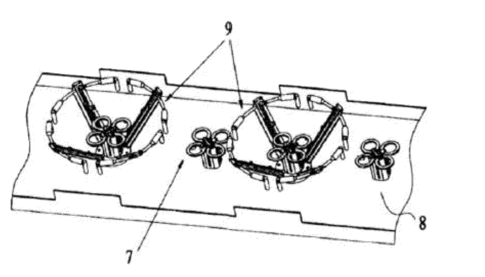
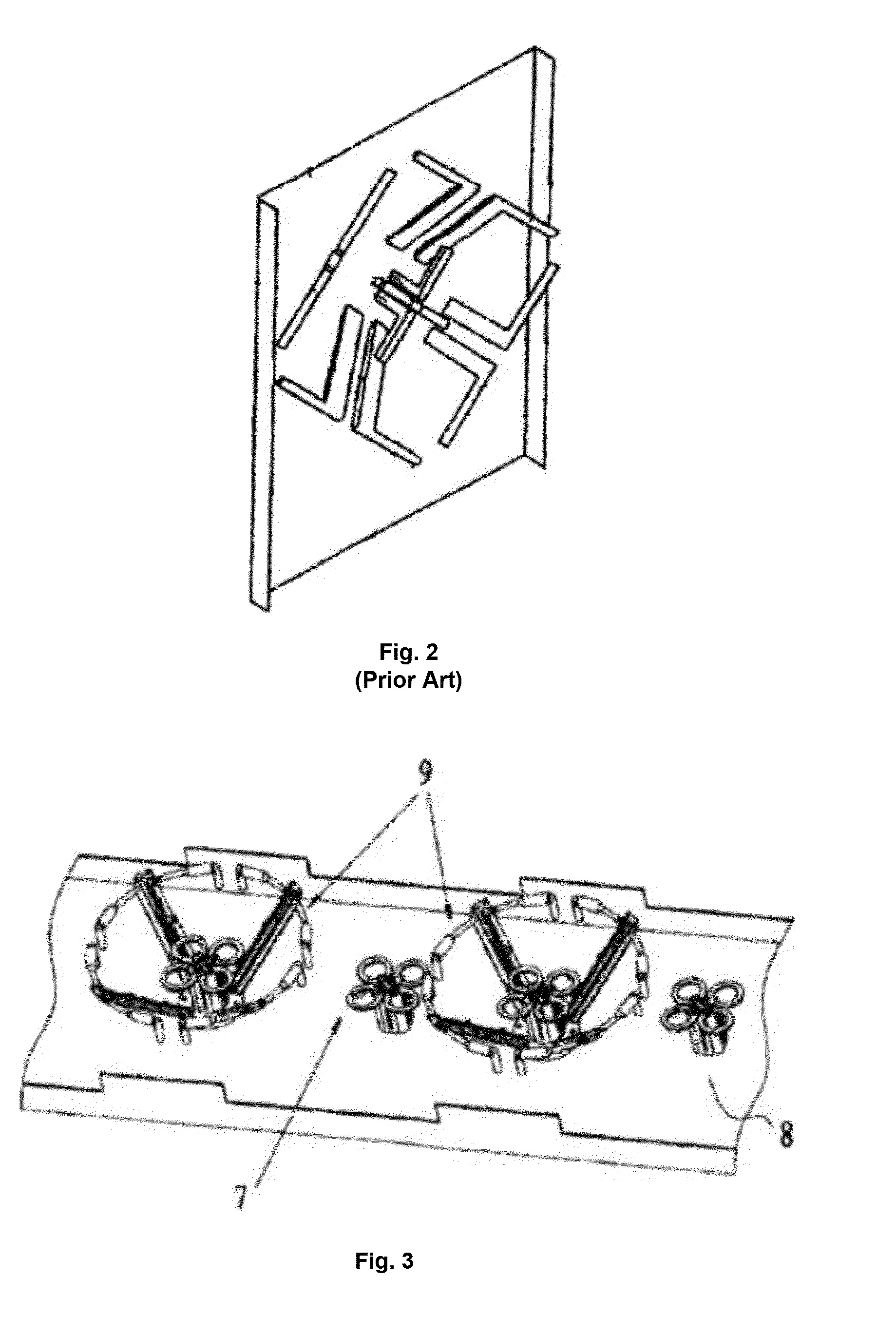
[0037]In a mobile communication antenna, radiation column elements (comprising low-frequency radiation column element and high-frequency radiation column element) are used for radiating communicating signals, which are typically formed by arranging a plurality of radiation units in a single-column matrix on a metal reflector. For high-frequency signals, the high-frequency radiation column element is formed by arranging a plurality of high-frequency radiation units at an equal distance in the axial direction of the same reference axis, and for the ease of subsequent description, the distance is defined as the second distance. Correspondingly, the low-frequency radiation column element is formed by arranging a plurality of low-frequency radiat...


PUM


Abstract

A multi-frequency array antenna, includes a reflective metal plate, a low-frequency radiation column element which is arranged on the reflective metal plate and operating in a first frequency band range, and a high-frequency radiation column element operating in a second frequency band range. The low-frequency radiation column element comprises several low-frequency radiation units arranged at an equal first distance in the axial direction of a first reference axis. The high-frequency radiation column element comprises several high-frequency radiation units arranged at an equal second distance in the axial direction of the first reference axis. The first distance is 2.5 times the second distance. At least one of the low-frequency radiation units is nested with one high-frequency radiation unit locationally corresponding thereto, and at least one of the low-frequency radiation units is axially located between two adjacent high-frequency radiation units close to the low-frequency radiation unit.

Description

FIELD OF THE INVENTION[0001]The present invention relates to the field of mobile communication, and in particular to a multi-frequency array antenna applicable for frequency bands of 2G, 3G and 4G.DESCRIPTION OF THE PRIOR ART[0002]Mobile communication is currently developing rapidly. In particular, 4G LTE mobile communication systems have been growing vigorously over recent years. At the same time, mobile communication operators have also intensified the effort to optimize 2G and 3G networks as much as possible to meet the demand for capacities and speed of communication systems. It is safe to say that 2G, 3G and 4G mobile communication systems will co-exist for a long time. As people have been paying increasingly high attention to electromagnetic radiation, the site selection and construction of new stations by operators often attract attention from and are resisted by residents living in the neighborhood. On the other hand, there is an urgent need for the expansion and reconstruct...

Claims


Application Information

Patent Timeline
Patent Type & Authority Applications(United States)
IPC IPC(8): H01Q5/20H01Q21/26H01Q19/10H01Q5/40
CPCH01Q5/20H01Q19/10H01Q21/26H01Q5/40H01Q1/246H01Q9/26H01Q19/106H01Q5/42
Inventor LIU, PEITAOJIA, FEIFEISUN, SHANQIU
Owner COMBA TELECOM TECH (GUANGZHOU) CO LTD
Why Eureka
Try Eureka