Self-Lubricating Slipring

a self-lubricating, slipring technology, applied in the direction of current collectors, electrical equipment, special surfaces, etc., can solve the problems of increased wear, extended life, and significant delay in opening other cavities, so as to improve the electrical contact and mechanical characteristics, reduce the wear of the surface, and store safe

Active Publication Date: 2015-10-08
SCHLEIFRING & APPBAU
View PDF13 Cites 12 Cited by
  • Summary
  • Abstract
  • Description
  • Claims
  • Application Information

AI Technical Summary

Benefits of technology

[0013]After the slip ring module or brush has been finished, it may be stored for a longer time, while the lubricant is enclosed and safely stored in the cavities. When the slip ring is used, a brush is sliding on the slip ring track, and therefore it slowly rubs off particles of the surface of the top coating. For this purpose it is preferred, if the slip ring track has a hardness, which is greater than the hardness of the top coating. It is further preferred, if the brush has a hardness, which is greater than the hardness of the top coating. When sufficient material is removed from the top coating, some cavities or pores are opened and release at least parts of their lubricant. This lubricant is distributed over the slip ring track by time and improves the electrical contact and mechanical characteristics, therefore further decreasing wear of the surface. Therefore, after the first or the first few cavities have been opened, the speed of opening further cavities slows down. This leads to a significant delay in opening other cavities, and further leads to an extended lifetime. In general, cavities are only opened when required due to lacking lubricant, which results in a slightly increased wear. To improve this process, it is preferred if the thickness of the top coating is varying. Furthermore, the process of release of lubricant may be controlled by modifying the pores or cavities. For example, the cavities may have a kind of bottleneck, which leads to a delayed release of lubricant. There may also be a variety of cavities with different properties. For example, there may be wide-open cavities for a quick release of lubricant, and there may be bottleneck cavities for a delayed release of lubricant, therefore allowing a further delay of release of the lubricant.

Problems solved by technology

This leads to a significant delay in opening other cavities, and further leads to an extended lifetime.
In general, cavities are only opened when required due to lacking lubricant, which results in a slightly increased wear.
For example, the cavities may have a kind of bottleneck, which leads to a delayed release of lubricant.

Method used


Image

  • Self-Lubricating Slipring
  • Self-Lubricating Slipring
  • Self-Lubricating Slipring

Examples


Embodiment Construction

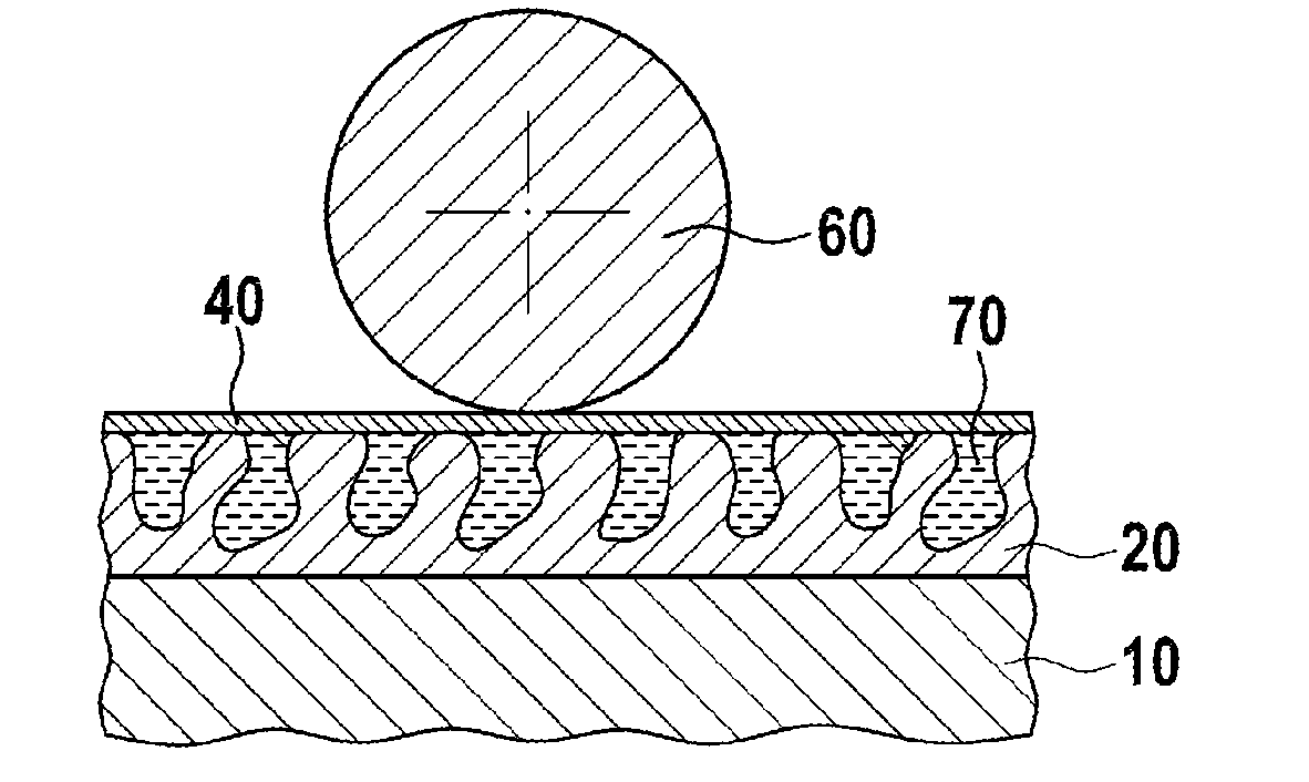
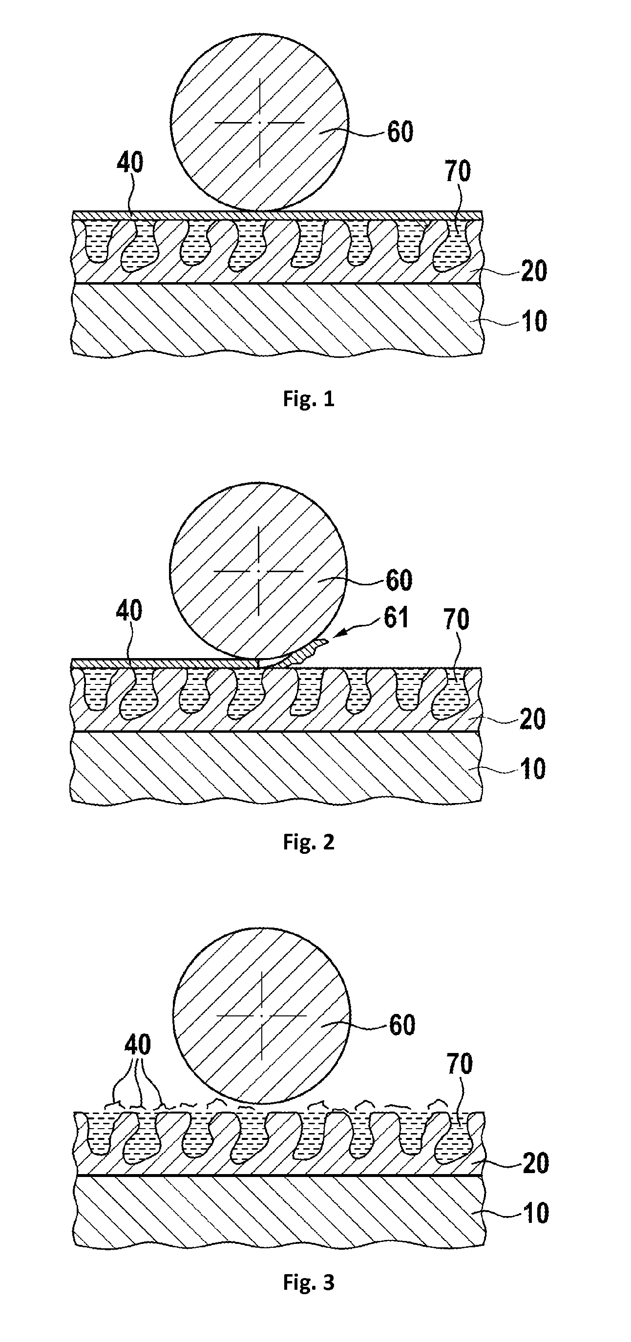
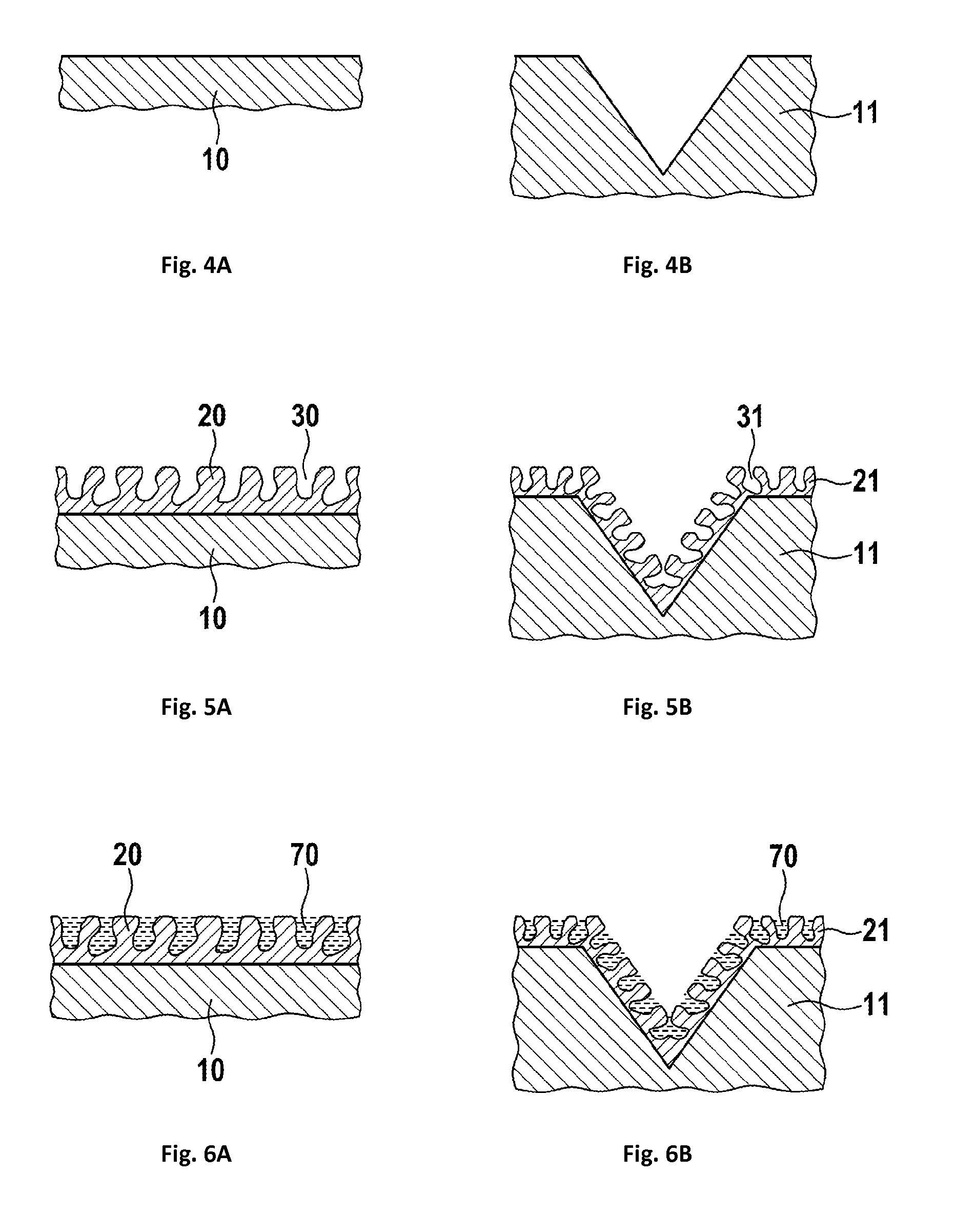
[0020]In FIG. 1, a slip ring track in a first embodiment is shown. A slip ring track 10, 11 has a contact area 20, 21 with a plurality of pores or cavities 30, 31. These cavities contain a lubricant 70. Furthermore, they are covered with a top coating 40, 41. A slip ring brush 60 which is a wire brush comprising a wire of conductive material is sliding on top of the top coating and on the contact area, when the top coating has been worn off. It is noted that the relations of sizes are not in scale. In general, the thickness of the contact area 20 is in an order of magnitude of some tenths of micrometers. A preferred range is between 30 and 100 micrometers. In contrast thereto, the diameter of a slip ring brush 60 is in the order of magnitudes of millimeters. A preferred range of diameter is between 0.1 millimeters and 3 millimeters. In all figures, the thickness of the contact area 20, the pores or cavities 30, and the top coating 40 have been enlarged to show more details.

[0021]In ...


PUM


Abstract

A slip ring has a slip ring track with a contact area, the contact area containing a plurality of pores or cavities. A lubricant is held within these pores and cavities and is enclosed by a top coating. When a slip ring brush is sliding over the slip ring track, it rubs off particles of the top coating, therefore opening some of the pores or cavities which release parts of the lubricant contained therein. This lubricant reduces surface friction of the slip ring brush at the slip ring track and therefore further wear, which results in an extended lifetime.

Description

PRIORITY CLAIM[0001]This application is a continuation of pending International Application No. PCT / EP2012 / 076036 filed on 18 Dec. 2012, which designates the United States, which is incorporated by reference in its entirety.BACKGROUND OF THE INVENTION[0002]1. Field of the Invention[0003]The invention relates to slip rings for transferring electrical power and / or signals between a rotating and a stationary part.[0004]2. Description of Relevant Art[0005]Electrical slip rings are used to transfer electrical power and / or signals between a rotating and a stationary part. Such devices are used in different applications, like wind energy plants or computer tomography scanners. There are also several military and aerospace applications. In all applications electrical current may be transferred continuously over a full rotation of the parts.[0006]It is common to all of these applications, that a high lifetime and a low contact resistance as well as a low contact noise are required. Furthermo...

Claims


Application Information

Patent Timeline
Patent Type & Authority Applications(United States)
IPC IPC(8): H01R39/56H01R39/08H01R43/10
CPCH01R39/56H01R39/08H01R43/10H01R39/22H01R43/12
Inventor HOLZAPFEL, CHRISTIAN
Owner SCHLEIFRING & APPBAU
Why Eureka
Try Eureka