
Semiconductor laser system for laser medical cosmetology

a laser system and semiconductor technology, applied in the field of semiconductor lasers, can solve the problems of low output power, small spot size, and low hair removal efficiency, and achieve the effect of reducing the contact area

Active Publication Date: 2015-10-15
FOCUSLIGHT TECH
View PDF1 Cites 5 Cited by
  • Summary
  • Abstract
  • Description
  • Claims
  • Application Information

AI Technical Summary

Benefits of technology

The coolers in the system have a very compact and stable structure, which allows the surface that comes into direct contact with skin to have a very low temperature. This makes the laser system more effective for medical treatment. The system also includes a collimating lens and an optical waveguide to produce very precise laser effects. This means that only one scan of the laser is needed to achieve the same or better effect compared to traditional methods. Additionally, a pair of light barriers is used to restrict the beams of the laser along a specific direction. Overall, the system provides a more efficient and effective solution for laser medical treatment.

Problems solved by technology

However, the system has a low output power, small spot size, and nonadjustable output wavelength, so the hair removal efficiency is very low.

Method used


Image

  • Semiconductor laser system for laser medical cosmetology
  • Semiconductor laser system for laser medical cosmetology
  • Semiconductor laser system for laser medical cosmetology

Examples


Embodiment Construction

[0053]Detailed description of the invention will be given below in conjunction with accompanying drawings.

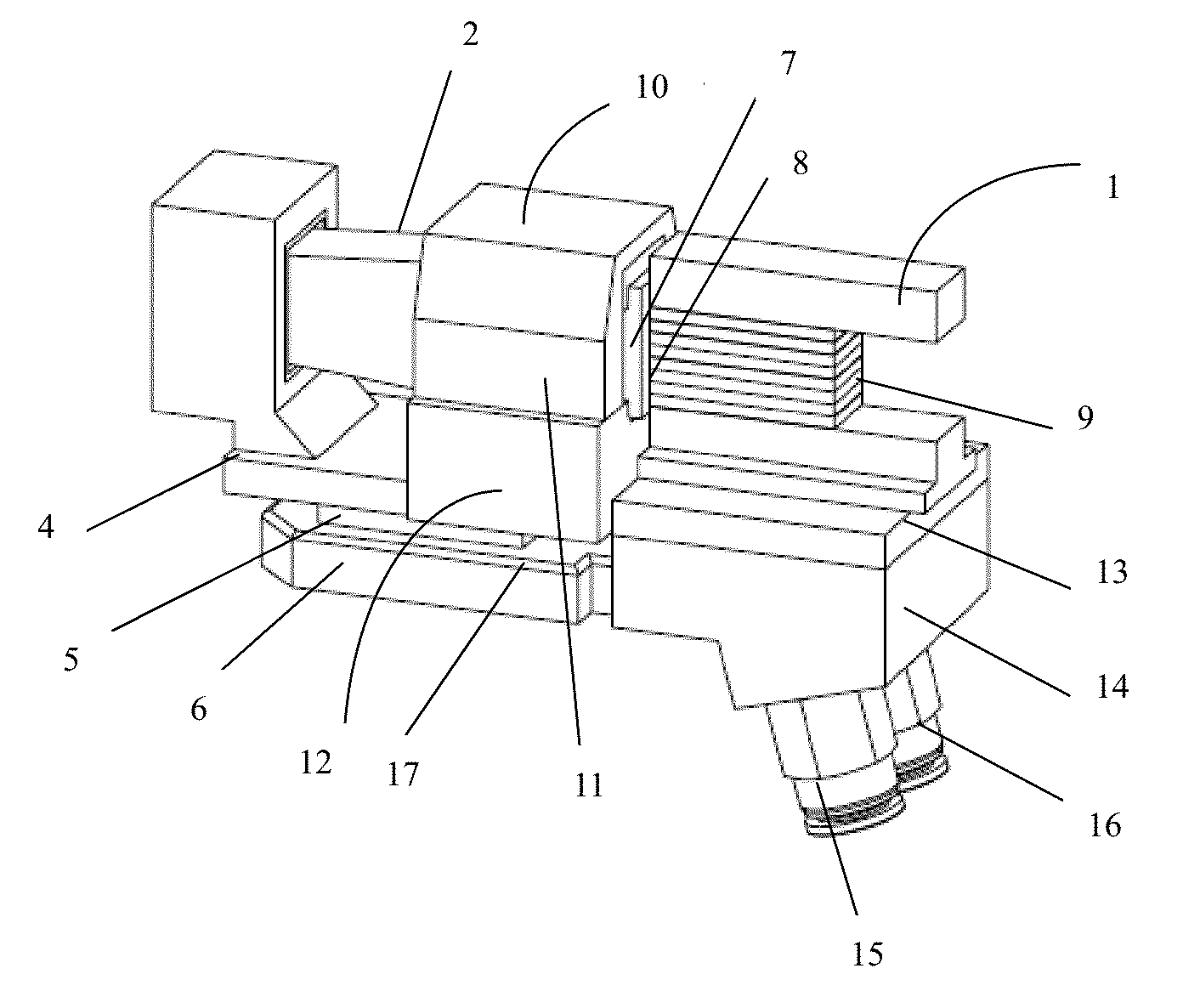
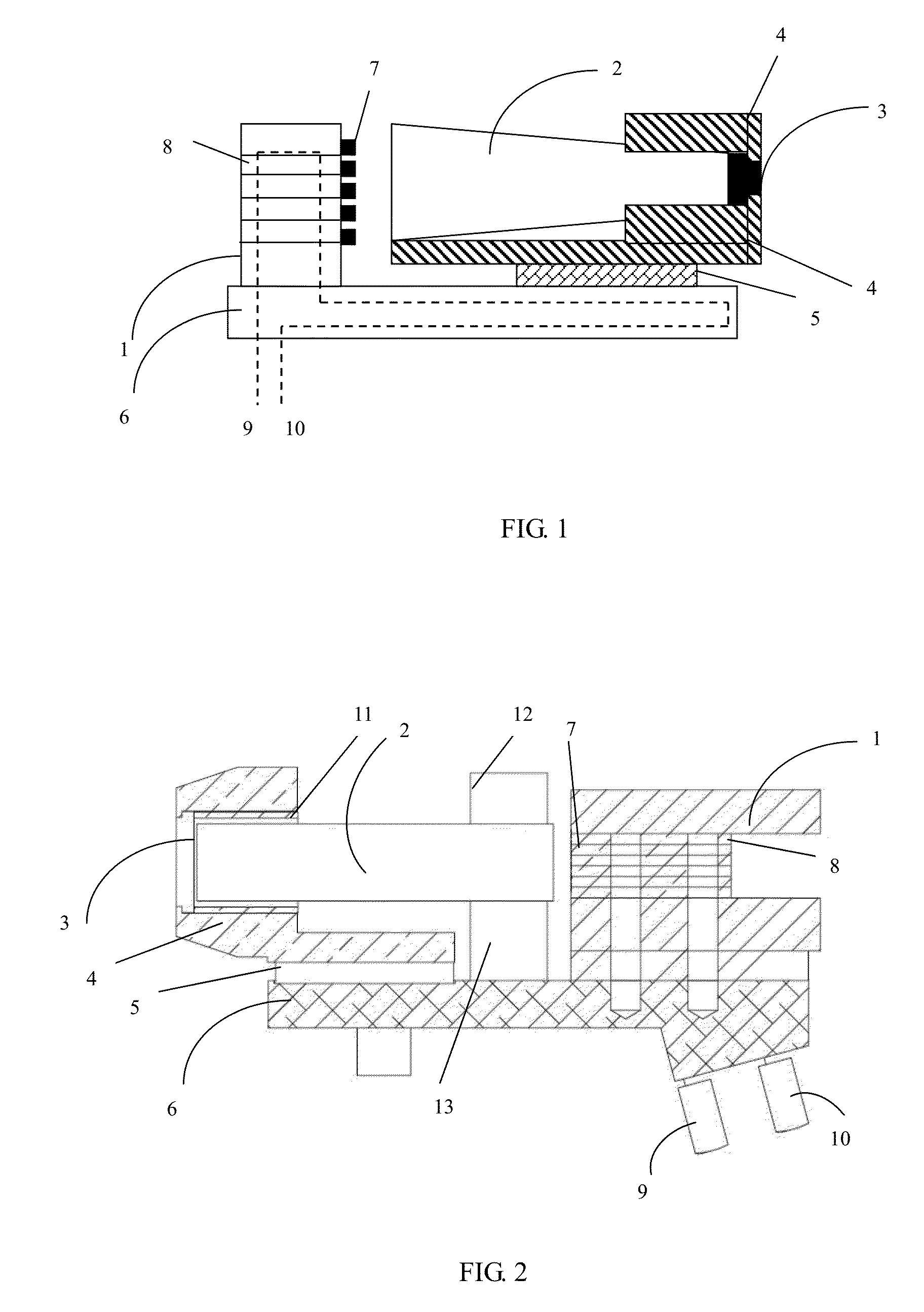
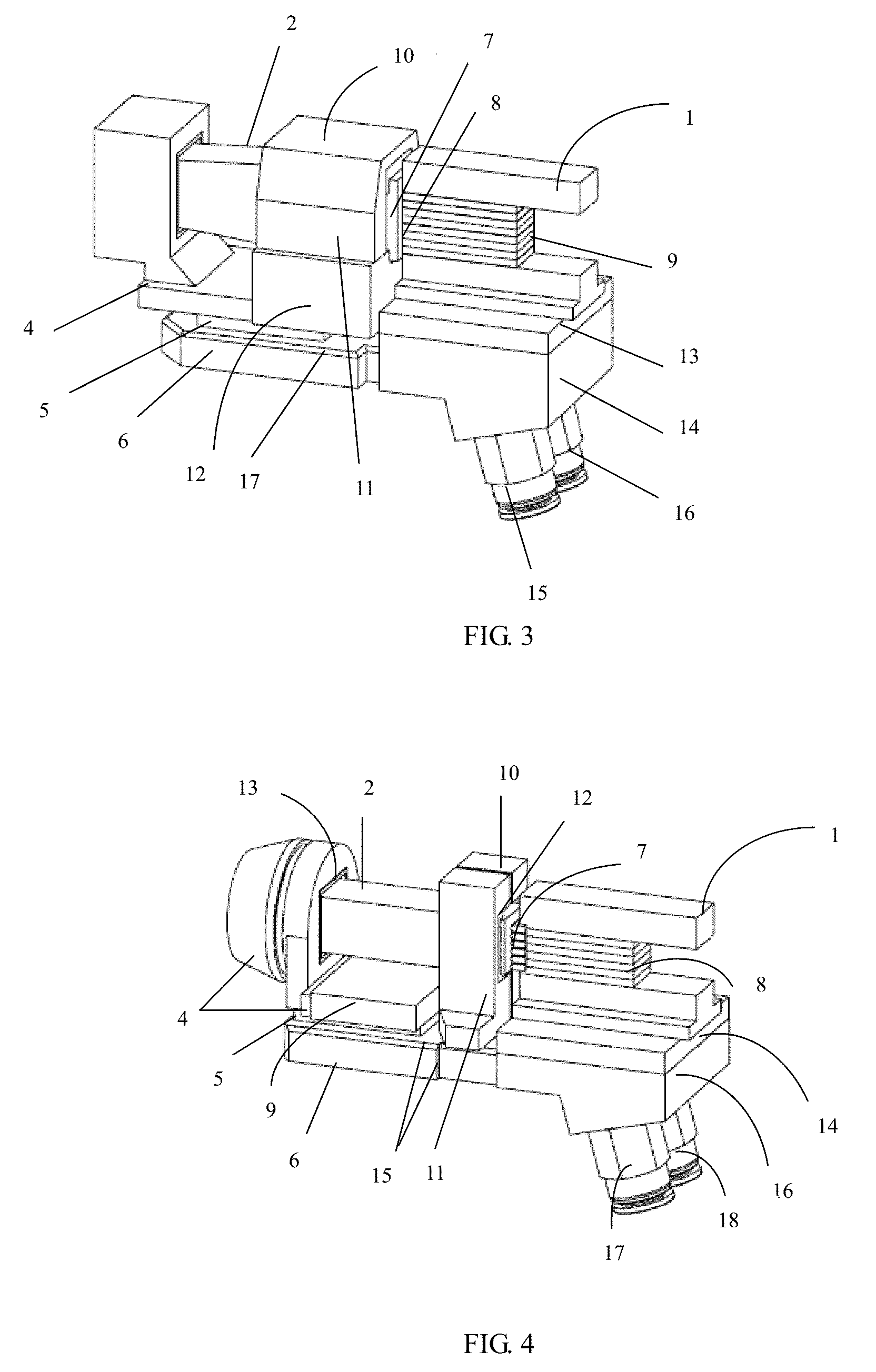
[0054]As shown in FIG. 1, each bar chip is welded on a heat sink to form a single bar laser. The semiconductor laser array 1 comprises a plurality of stacked single bar lasers, so that the output power of the semiconductor laser array exceeds 200 W.

[0055]The optical waveguide 2 is disposed at the light emitting end of the semiconductor laser array 1, totally reflecting and outputting the laser beams. The space between the optical waveguide and the light emitting surface of the semiconductor laser array is between 0.5 and 5.0 mm. Most of the laser energy is constrained and transmitted in the optical waveguide and cannot spill over. In practice, if the optical waveguide is a metal, it should be hollow, and the four inner sides thereof should be plated with reflective films. Optionally, the optical waveguide can be made of transparent material, such as glass, resin, sapphire and di...


PUM


Abstract

A semiconductor laser system for laser medical cosmetology, comprising a semiconductor laser array (1), an optical waveguide (2), a boss-shaped transparent contact window (3) located at the light outlet end of the optical waveguide (2), and a refrigeration block (4) for conduction cooling of the contact window (3); the refrigeration block (4) consists of a base portion and a hollow head above the base portion; the front part of the hollow head presses against and is tightly fastened to the whole side wall of the contact window (3); the light outlet end of the optical waveguide (2) is located in the cavity of the hollow head, and has a gap between the waveguide and the inner wall of the hollow head; a thermoelectric semiconductor refrigerator (5) is disposed below the base portion of the refrigeration block (4); a first water supply block (6) is disposed below the thermoelectric semiconductor refrigerator (5); and a second water supply block (16) for heat dissipation is installed in the semiconductor laser array (1). The system employs a unique refrigeration structure design so as to cause the temperature of the face of the working end in direct contact with skin to approach the freezing point, and the structure is compact and stable.

Description

FIELD OF THE INVENTION[0001]The invention relates to the use of a semiconductor laser, and more particularly to a semiconductor laser system for medical cosmetology.BACKGROUND OF THE INVENTION[0002]As an important application field of laser, laser medical treatment has developed quickly in recent years and gradually matured. Featuring small size, light weight, long service life, low power consumption, broad wavelength coverage, etc., semiconductor lasers are particularly suitable for the manufacturing of medical facilities.[0003]Typical laser hair removal facilities include ruby laser (wavelength of 694 nm), alexandrite laser (wavelength of 755 nm), semiconductor laser (wavelength of 810 nm), and Q-switched Nd YAG laser (wavelength of 1064 nm), among which, the semiconductor laser has been proved as a safe and effective hair removal tool.[0004]It is estimated that in 2010 there are about 5 million person times of laser hair removal surgery all over the world. Another important appli...

Claims


Application Information

Patent Timeline
IPC IPC(8): A61B18/20H01S5/00H01S5/024H01S5/40
CPCA61B18/203H01S5/4025H01S5/02415H01S5/02446H01S5/005A61B2018/00005H01S5/02407H01S5/02438H01S5/4031
Inventor LIU, XINGSHENGDAI, YESUN, YAOWU, DIZONG, HENGJUNTONG, LISHUNCAI, LEI
Owner FOCUSLIGHT TECH
Learn More