
Optically Transparent Films for Measuring Optically Thick Fluids

a technology of optically thick fluids and transparent films, applied in the direction of optical radiation measurement, instruments, borehole/well accessories, etc., can solve the problems of inability to detect absorption that is barely detectable for a second analyte, and the state-of-the-art optical measurement techniques are difficult to apply

Active Publication Date: 2015-10-15
HALLIBURTON ENERGY SERVICES INC
View PDF7 Cites 12 Cited by
  • Summary
  • Abstract
  • Description
  • Claims
  • Application Information

AI Technical Summary

Benefits of technology

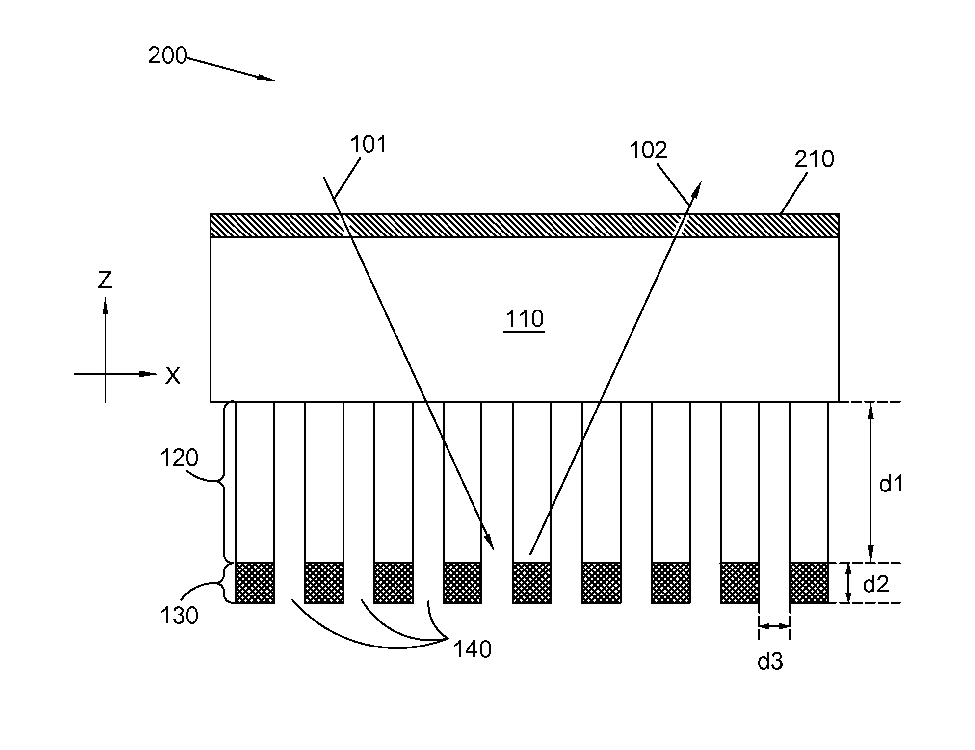
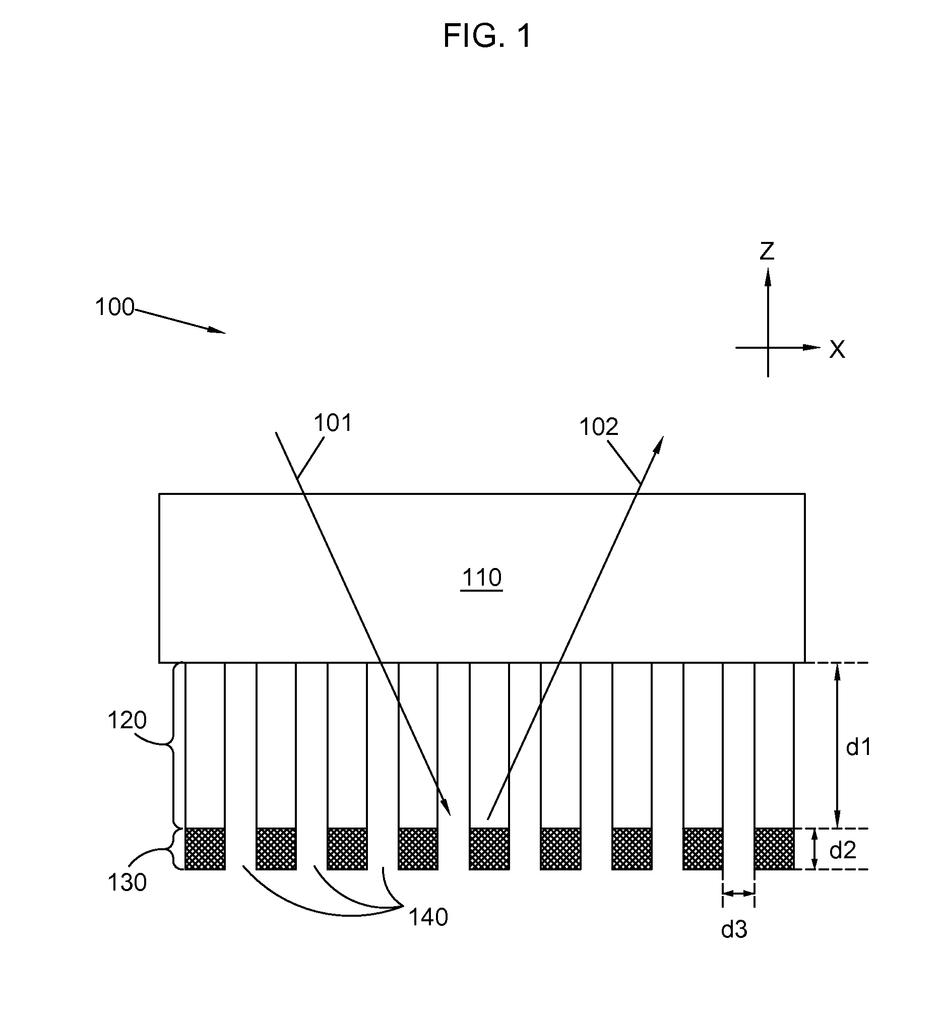
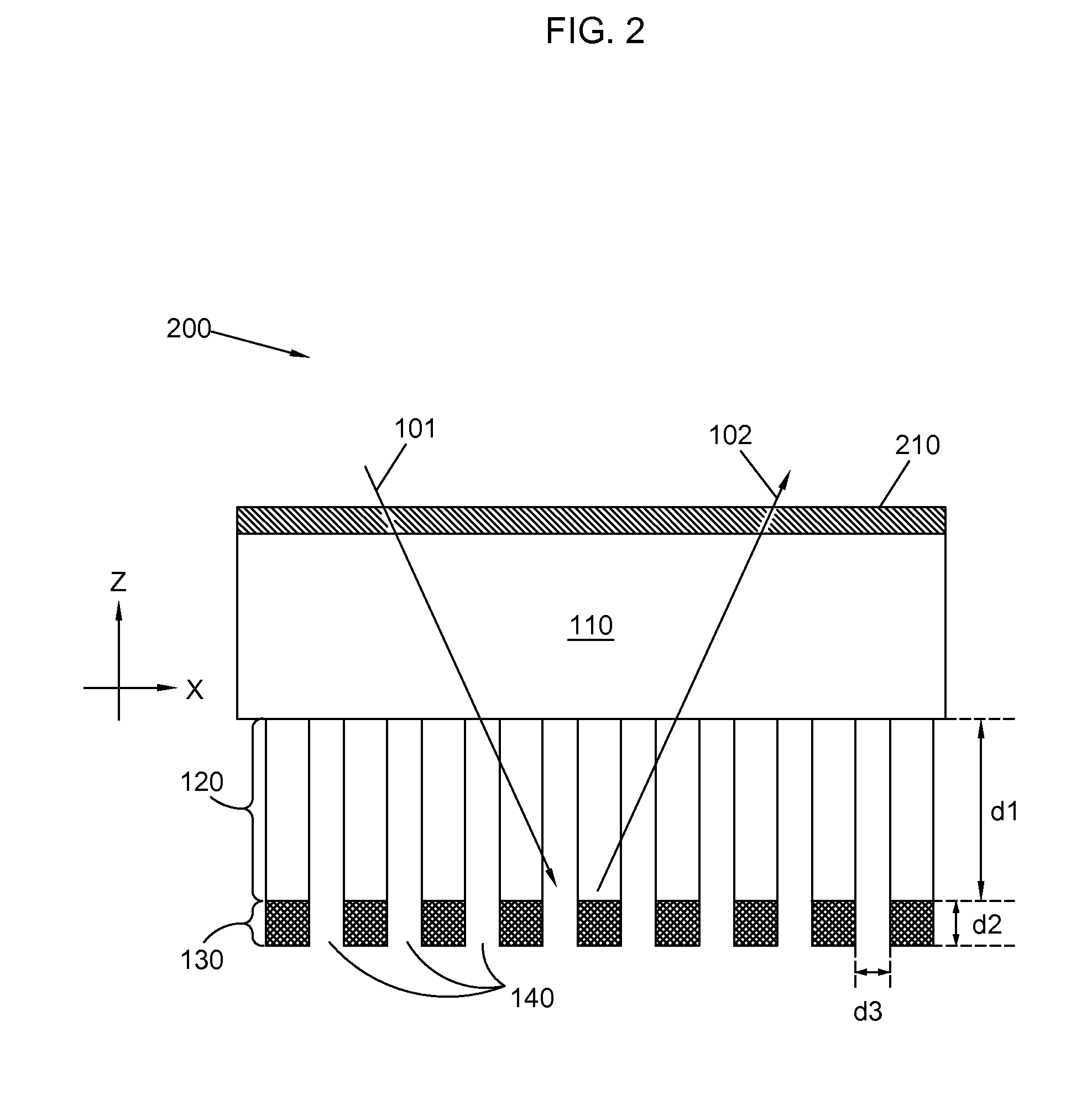
This patent describes a multilayered film for making spectroscopic measurements in fluids. The film has a substrate, a porous layer, and a reflective layer. The porous layer allows components of the fluid to be optically measured when the film is immersed in the fluid. A sensor made from this film can be used to measure properties of the fluid by directing an input light through the substrate and detecting the output light. The patent also describes a method of manufacturing the film by cleaning an optically transparent substrate, applying a voltage to the substrate in a phosphoric acid solution to form a porous alumina layer, and forming a reflective layer on the surface of the porous alumina layer.

Problems solved by technology

State-of-the-art optical measurement techniques are difficult to apply in hydrocarbon exploration and extraction due to the opaque nature of crude oil samples for a broad spectral wavelength region, covering from the visible and near infrared (400 nm-2500 nm) to the mid-infrared and beyond (3500 nm-10 μm).
In many instances large particulates and components may not be of interest for a measurement, since they may be easily removed from the fluid at a later stage in refinement.
Another problem encountered in crude oil samples is that the many analytes of interest within the sample may have considerably different contributions to the OD of the sample.
For example, a small optical path length may result in considerable light absorption for a first analyte, while resulting in absorption that is barely detectable for a second analyte.
Traditional spectroscopic measurements may also have the problem of highly absorbing samples being ‘masked out’ by an optical path length that may be too long.
Thus, a component of light having certain wavelength may be completely or almost completely absorbed by an analyte before the light goes through the sample, impeding determination of analyte concentration.

Method used


Image

  • Optically Transparent Films for Measuring Optically Thick Fluids
  • Optically Transparent Films for Measuring Optically Thick Fluids
  • Optically Transparent Films for Measuring Optically Thick Fluids

Examples


Embodiment Construction

[0027]Optical absorption measurement techniques include measuring an output signal intensity ‘Iout’ and comparing it to an input signal intensity ‘Iin’. The signal intensity ‘Iout’ may be the intensity of an input signal ‘Iin’ traversing a thickness of a sample, or optical path. The output signal may be measured in transmittance or reflectance mode. According to the Beer-Lambert law of absorption, for a monochromatic light beam having wavelength ‘λ’ and a negligible cross-section, the relation between Iout(λ) and Iin(λ) is given by

Iout(λ)=Iin(λ)·10−A(λ)  (1)

[0028]In Eq. (1), the absorbance A(λ) is a property of the material and the optical setup, including an optical path length ‘I(λ)’ (usually in cm), and a concentration ‘C’ of the analyte absorbing radiation at a wavelength, λ. The transmittance, Tλ, of a material is given as the ratio of Iout(λ) / Iin(λ) (cf. Eq(1)). The absorbance A(λ), in Eq. (1) may be written as

A(λ)=ε(λ)·l(λ)·C  (2)

where E(λ) is the molar absorptivity (mol−1·cm...


PUM

PropertyMeasurementUnit
spectroscopic measurementsaaaaaaaaaa
optical densitiesaaaaaaaaaa
transparentaaaaaaaaaa

Abstract

A multilayered film and a method for performing spectroscopic measurements in a fluid are provided. The multilayered film includes a substrate; a porous layer adjacent to the substrate; and a reflective layer formed on the porous layer, wherein the porous layer selectively allows a component of a fluid to be optically measured when the multilayered film is immersed in the fluid. A sensor for spectroscopic measurements in crude oil samples including a multilayered film as above is also provided. A method of manufacturing a multilayered film for spectroscopic measurements in fluids as above is also provided.

Description

BACKGROUND[0001]1. Technical Field[0002]Embodiments disclosed herein relate to the field of thin film optical devices for spectroscopic measurements of a fluid. In particular, embodiments disclosed herein relate to multilayered films for spectroscopic measurements of optically thick fluids.[0003]2. Description of Related Art[0004]In the field of oil exploration and extraction there is often the need to perform measurements of fluid samples that are optically thick, or opaque. Optical Density (OD) is a property of a material that measures the attenuation of light of a certain wavelength traversing through a portion of the material. The OD or opaqueness of a material is due to absorption and scattering of the light by molecules forming the material. Examples of wavelength dependent light absorbing phenomena are electronic transitions (visible) and vibration and rotational modes (near-infrared and mid-infrared) of the materials in the sample. Scattering of light arises from interaction...

Claims


Application Information

Patent Timeline
Patent Type & Authority Applications(United States)
IPC IPC(8): G01N21/3577G01N21/39C25D5/12C25D9/04C25D5/48C25D5/10C25D7/00G01N33/28C25D5/52
CPCG01N21/3577G01N33/2823G01N21/39C25D5/12G01N2201/0612C25D5/48C25D5/10C25D7/00C25D9/04C25D5/52E21B49/08G01N21/31G01N21/031G01N2201/0668G01N21/0303C25D5/627C25D5/623
Inventor PERKINS, DAVID L.
Owner HALLIBURTON ENERGY SERVICES INC
Learn More