
Method and apparatus for performing de-skew control

a technology of deskew and control method, applied in the field of method and apparatus for performing deskew control, can solve the problems of data skew, large hardware structure, and inability to meet the needs of data transmission, so as to improve data transmission performance, and improve the effect of data transmission performan

Active Publication Date: 2015-10-15
FARADAY TECH CORP
View PDF4 Cites 6 Cited by
  • Summary
  • Abstract
  • Description
  • Claims
  • Application Information

AI Technical Summary

Benefits of technology

The present invention provides a method and an apparatus for improving data transmission performance by controlling the timing of data transmission. This method and apparatus can control the timing of data transmission without causing complications, such as large hardware size and long latency. Overall, this invention can improve data transmission performance without introducing side effects.

Problems solved by technology

Data skew is one of the problems possibly encountered when a traditional electronic device is performing data transmission.
However, new problems such as some side effects are thereby introduced.
This makes the entire hardware structure (more particularly, the sizes of buffers and sizes of clock sources) too large, and also raises related production cost.
This makes the entire hardware structure too complicated.
More particularly, a lot of extra control signals are required for controlling the data flow.
Yet another conventional method attempts to directly move a certain predetermined symbol to the first bit, which makes the traditional electronic device incompatible with new structures and have a quite long latency.

Method used


Image

  • Method and apparatus for performing de-skew control
  • Method and apparatus for performing de-skew control
  • Method and apparatus for performing de-skew control

Examples


Embodiment Construction

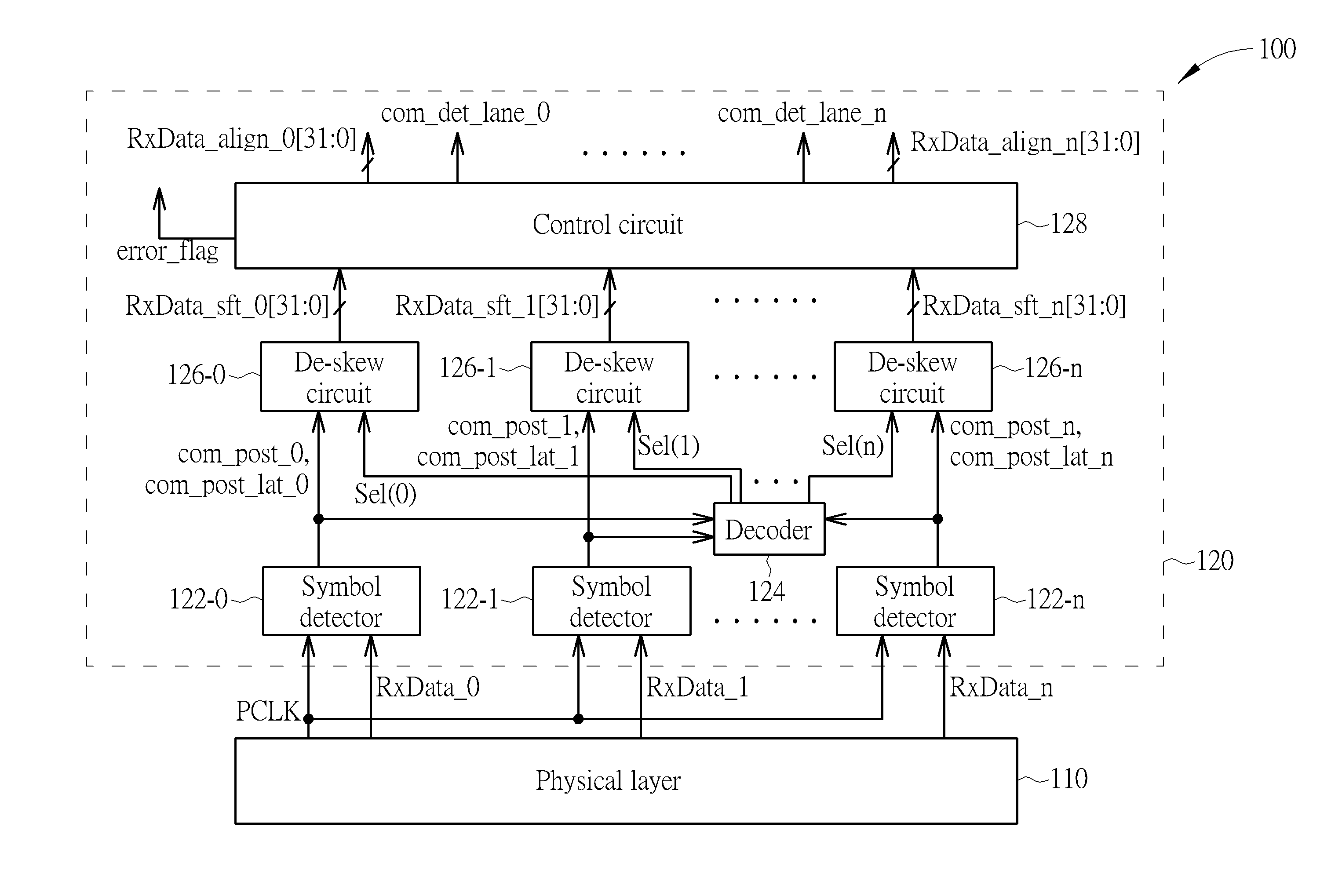
[0022]Please refer to FIG. 1, which is a diagram illustrating an apparatus 100 arranged for performing de-skew control according to a first embodiment of the present invention. The apparatus 100 includes at least a portion (e.g., part or all) of an electronic device. For example, the apparatus 100 may include a control circuit of the electronic device, such as a control circuit implemented with an Integrated Circuit (IC). For another example, the apparatus 100 may include the entire electronic device, such as the electronic device itself. For yet another example, the apparatus 100 may be a system including the electronic device, such as a computer system. Examples of the electronic device may include, but not limited to, a personal computer, an external storage equipment (e.g., an external hard drive), or an inner module of a personal computer. According to this embodiment, the electronic device includes a plurality of lanes, such as lane 0, lane 1, . . . , lane n, for performing da...


PUM


Abstract

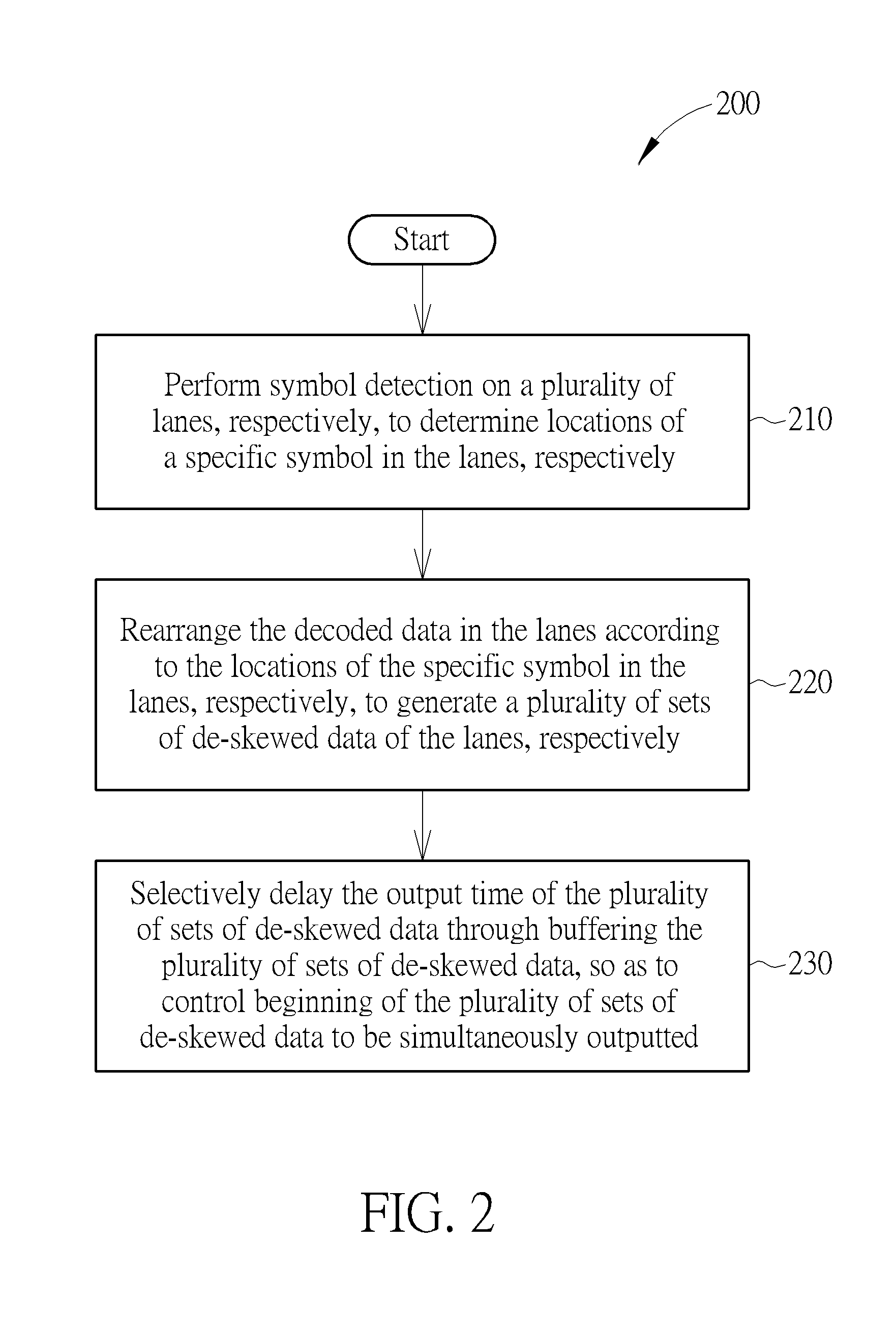
A method and apparatus for performing de-skew control are provided, where the method is applied to an electronic device. The method includes the steps of: performing a symbol detection at a plurality of lanes of the electronic device, respectively, to determine locations of a specific symbol at the plurality of lanes, respectively; according to the locations of the specific symbol at the plurality of lanes, selectively rearranging decoded data in the plurality of lanes to generate a plurality of sets of de-skewed data respectively corresponding to the plurality of lanes; and by buffering the plurality of sets of de-skewed data, selectively delaying output of the plurality of sets of de-skewed data to control beginning of the plurality of sets of de-skewed data to be simultaneously output.

Description

BACKGROUND OF THE INVENTION[0001]1. Field of the Invention[0002]The present invention relates to solving a data skew issue of an electronic device having a plurality of lanes, and more particularly, to a method and an apparatus for performing de-skew control.[0003]2. Description of the Prior Art[0004]Data skew is one of the problems possibly encountered when a traditional electronic device is performing data transmission. For example, the traditional electronic device may have a peripheral component interconnect (PCI) express port arranged to communicate with external device(s). For another example, the traditional electronic device may have a PCI express bus for allowing a plurality of internal modules in the traditional electronic device to communicate with each other. In related arts, the traditional electronic device usually needs various extra control mechanisms, to solve the data skew problem. However, new problems such as some side effects are thereby introduced. For example,...

Claims


Application Information

Patent Timeline
Patent Type & Authority Applications(United States)
IPC IPC(8): G01R31/317
CPCG01R31/31727G01R31/31725
Inventor CHANG, CHING-SHENGHU, YUAN-MIN
Owner FARADAY TECH CORP
Learn More