
Optically-actuated mechanical devices

Active Publication Date: 2015-10-22
ARMY UNITED STATES OF AMERICA AS REPRESENTED BUY THE SEC OF THE THE +1
View PDF0 Cites 20 Cited by
  • Summary
  • Abstract
  • Description
  • Claims
  • Application Information

AI Technical Summary

Benefits of technology

The present invention relates to optically-actuated mechanical devices and their actuation using optically-sensitive materials. The devices comprise a deformable section that is formed of an element with an intrinsic stress differential or gradient, and an optically-sensitive material that prevents deformation when heated by absorbing optical energy. The optically-sensitive material can be an optically-sensitive polymer or a thermally-sensitive shape memory alloy. The devices can be used in various applications such as micro-grippers or switches. The methods for fabricating and actuating the devices involve depositing material on a substrate, patterning the device, and applying optically-sensitive material. The optical energy used for actuation has a wavelength between about 1.4 and 1.8 μm or other wavelengths.

Problems solved by technology

These direct actuation means, however, require large, bulky modules, which can be difficult to integrate within micro-systems, such as batteries or power supplies.
However, voltage outputs are typically low, and overall photovoltaic optical-to-electrical conversion efficiencies are typically very low (e.g., 10%, up to 22% for specific wavelengths, and over 40% for cooled, multi-junction, commercial research cells).
But, these systems have shown low efficiency of RF power transfer due to the small-sized antennas which must be with micro-systems.
Additionally, thermal or chemical activation mechanisms also have been proposed as alternatives, but these have not been found to be readily controlled in a practical manner.
However, each of these conventional examples of optical actuation may be characterized as requiring either high irradiance levels (e.g., >1 W / cm2), long actuation times (10's to 100's of seconds), bulk films and / or materials which are not readily amenable to lithographic patterning and micro-fabrication.

Method used


Image

  • Optically-actuated mechanical devices
  • Optically-actuated mechanical devices
  • Optically-actuated mechanical devices

Examples


Embodiment Construction

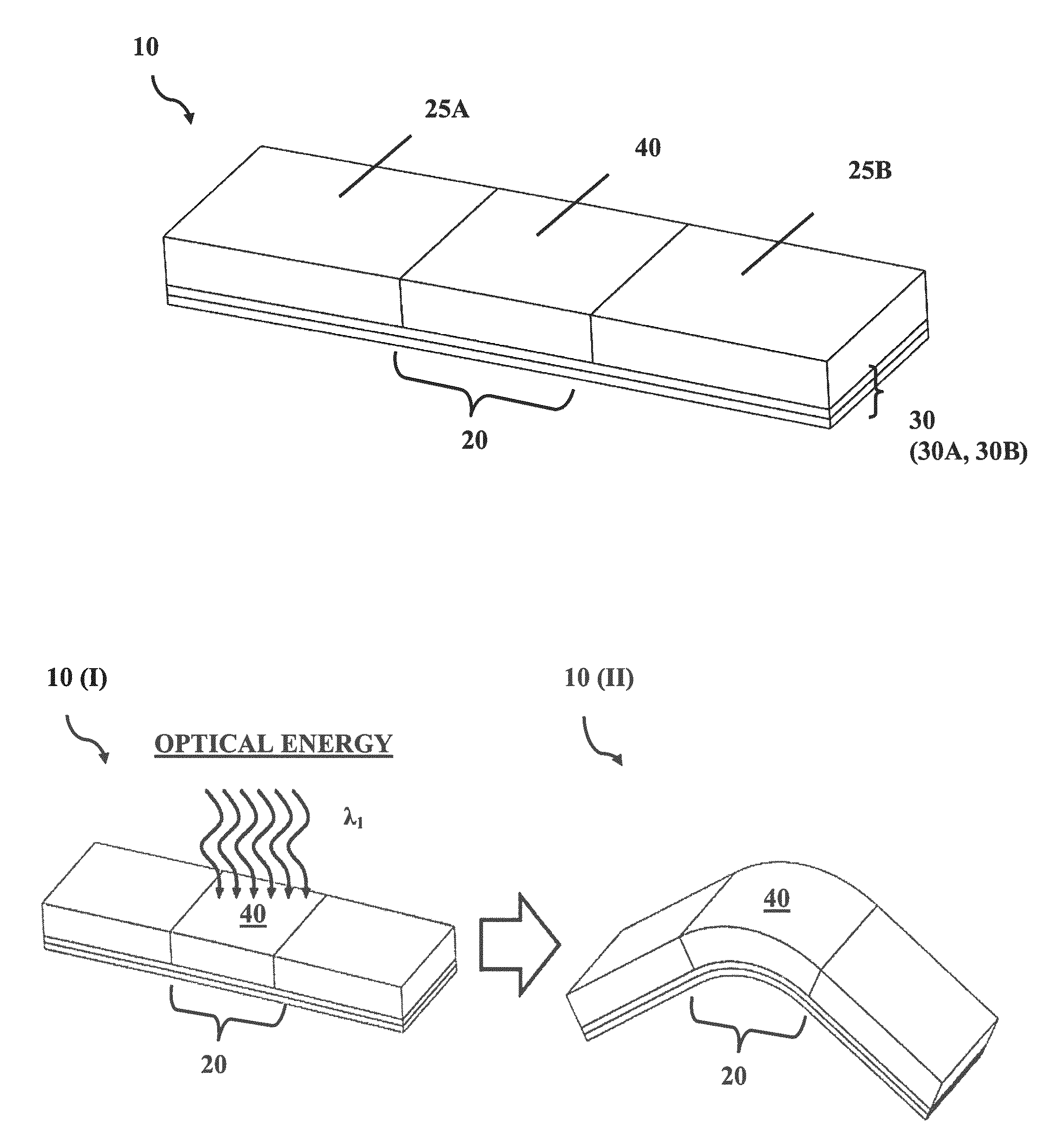
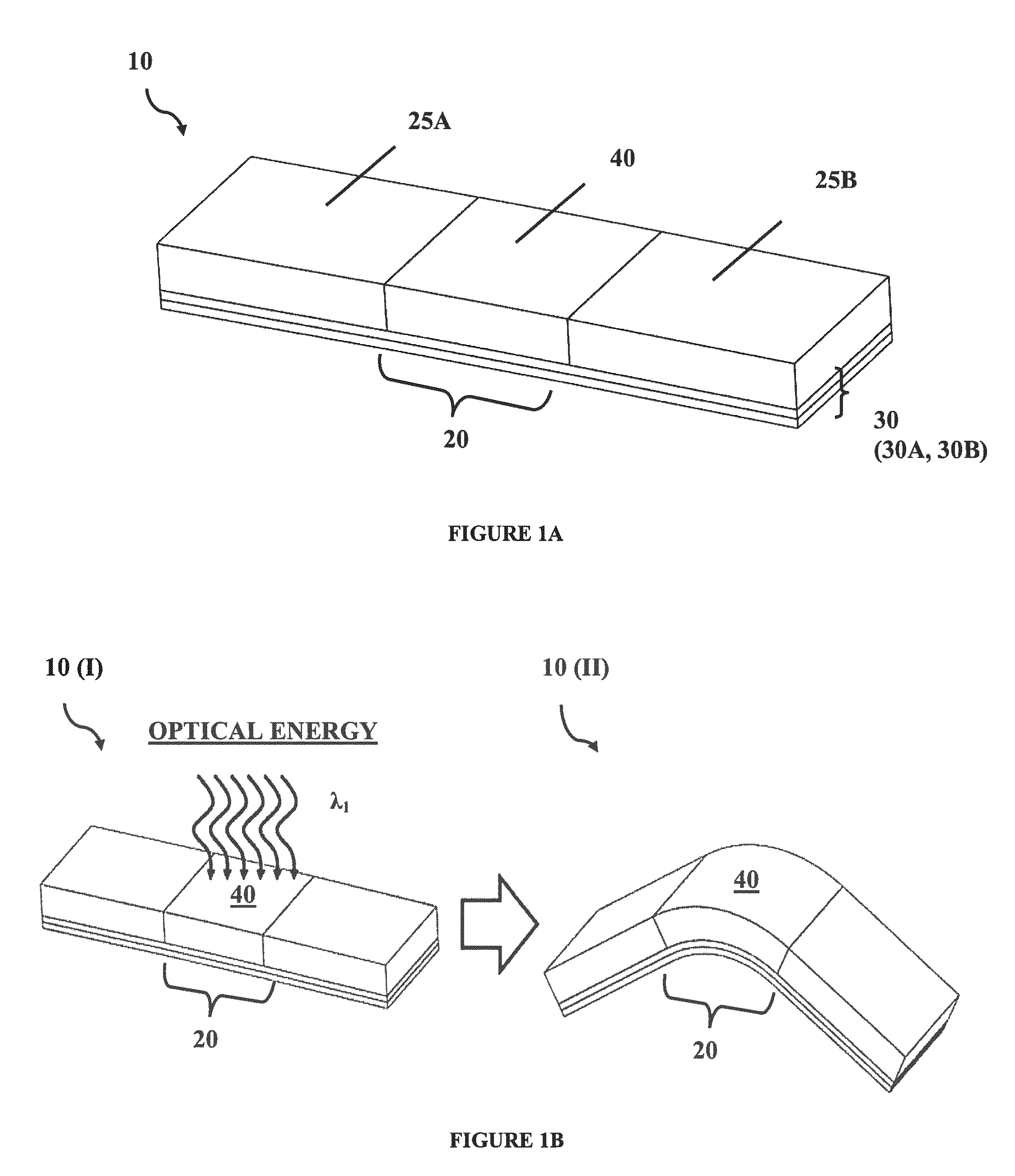
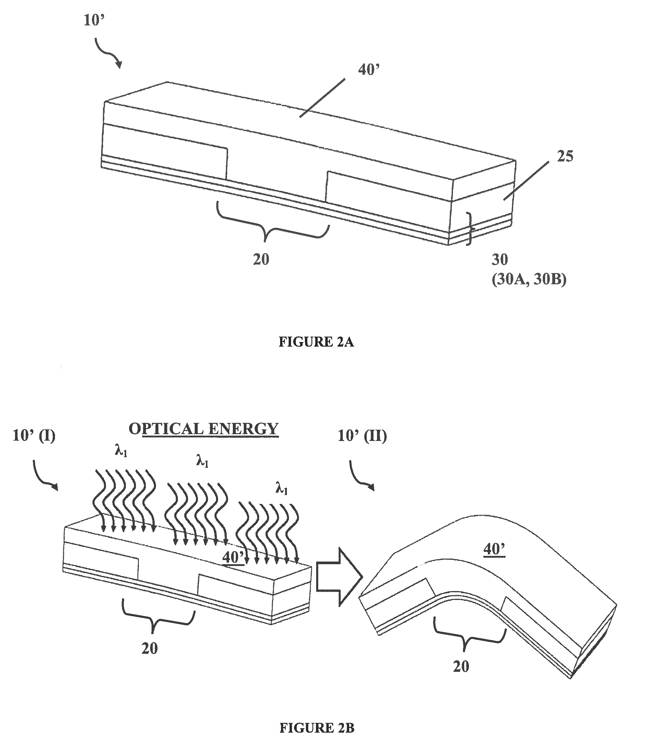
[0025]Various optically-actuated mechanical devices are described which are capable of providing mechanical actuation, without the need of any attached batteries, wires, or other tethers. Embodiments of the invention generally address the need to develop new wireless power transfer and new actuation schemes for micro-systems, such as MEMS.

[0026]In general, the optically-actuated mechanical devices are configured to be actuated using optical energy. The optical energy includes electromagnetic radiation or light in the optical spectra, which generally include various spectra and sub-bands within ultraviolet (UV), visible (VIS), and / or infrared (IR) light.

[0027]The devices include one or more deformable sections which permit deformation of the device in some way, an element effecting that deformation, and optically-sensitive material which when optically-activated by absorbing optical energy enables the deformation.

[0028]Upon illumination of the optically-sensitive material (e.g., with...


PUM


Abstract

According to embodiments, an optically-actuated mechanical device comprises at least one deformable section formed of: an element including an intrinsic stress differential or gradient, the stress tending to urge deformation of one portion relative to another portion; and an optically-sensitive material which is configured to (i) initially prevent deformation of the device, and (ii) upon sufficient heating by absorbing optical energy allows the element to deform. The devices may be incorporated into various devices and apparatuses for select, non-contact actuation using only optical energy, for example, via light, from one or more lasers. Methods for fabricating and actuating such devices are also disclosed.

Description

RELATED APPLICATION(S)[0001]This application claims the benefit of U.S. Provisional Patent Application No. 61 / 839,572 filed on Jun. 26, 2013, which is herein incorporated by reference in its entirety for all purposes.GOVERNMENT INTEREST[0002]Governmental Interest—The invention described herein may be manufactured, used and licensed by or for the U.S. Government. Funding of research underlying the innovative technology of this invention came, at least in part, from Contract No. W911NF-09-2-0065.FIELD OF INVENTION[0003]Embodiments of the present invention generally relate to micro-mechanical actuator devices, such as MEMS, and more particularly to optically-actuated mechanical devices and the actuation thereof.BACKGROUND[0004]Micro-electrical-mechanical systems (MEMS) have been incorporated into many systems, for various civilian and military applications. Many MEMS actuators use direct electrical, pneumatic, or fluidic actuation. These direct actuation means, however, require large, ...

Claims


Application Information

Patent Timeline
IPC IPC(8): B25J15/12B25J7/00B25J15/10
CPCB25J15/12B25J7/00B25J15/10F03G7/00
Inventor MORRIS, CHRISTOPHER J.MALACHOWSKI, KATE E.GRACIAS, DAVID H.DUBEY, MADAN
Owner ARMY UNITED STATES OF AMERICA AS REPRESENTED BUY THE SEC OF THE THE
Features
  • Generate Ideas
  • Intellectual Property
  • Life Sciences
  • Materials
  • Tech Scout
  • Unparalleled Data Quality
  • Higher Quality Content
  • 60% Fewer Hallucinations
Learn More