
Method for Separating a Carbon Dioxide-rich Gas by Partial Condensation and Permeation

a carbon dioxide and gas technology, applied in gas treatment, lighting and heating apparatus, inorganic chemistry, etc., can solve the problems of complex recycling of fluids in exchangers, large temperature drop in the inlet gas of membranes and permeates, and degraded performance or even integrity, so as to reduce the flow area of permeates and optimize the system , the volume flow rate of gas is very high

Inactive Publication Date: 2015-10-22
LAIR LIQUIDE SA POUR LETUDE & LEXPLOITATION DES PROCEDES GEORGES CLAUDE
View PDF7 Cites 7 Cited by
  • Summary
  • Abstract
  • Description
  • Claims
  • Application Information

AI Technical Summary

Benefits of technology

The present invention relates to a method for preventing excessively low temperatures during the recycling of cooling from membranes in a system. The invention suggests increasing the operating temperature of the membranes by warming the top of the pot. This helps recycle the low-temperature cold against hotter fluids, minimizing energy losses during heat exchanges. The invention also suggests adapting the pressure drop in the permeate pass of the membranes exchangers. Choosing high-pressure drops decreases the flow area of the permeate and reduces the size of the exchanger. The invention also describes a permeation unit that allows for a single permeatation step and pre-heating of the permeate and residue in a heat exchanger. The technical effects of the invention include improving the efficiency and reducing the size of the membrane cooling system.

Problems solved by technology

The loss of pressure between the inlet gas of the membranes and the permeate involves a large temperature drop.
Furthermore, since the gas resulting from the condensation pot is at phase equilibrium and close to the triple point, an excessively large temperature drop could liquefy CO2, or even freeze it in the membrane, which could degrade its performances or even threaten its integrity.
Finally, if the temperature of the residue and / or of the permeate drops below the temperature of the triple point (which will easily be achieved for high membrane yields), recycling the cold from these fluids in an exchanger will prove complex.
The skin temperature at the exchange (tubes or plates for example) would then be very low and the risks of solidification of the CO2 to be cooled would be very high.

Method used


Image

  • Method for Separating a Carbon Dioxide-rich Gas by Partial Condensation and Permeation
  • Method for Separating a Carbon Dioxide-rich Gas by Partial Condensation and Permeation
  • Method for Separating a Carbon Dioxide-rich Gas by Partial Condensation and Permeation

Examples


Embodiment Construction

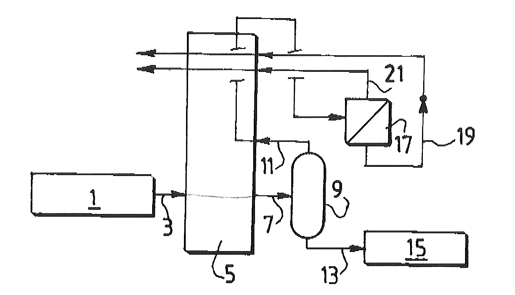
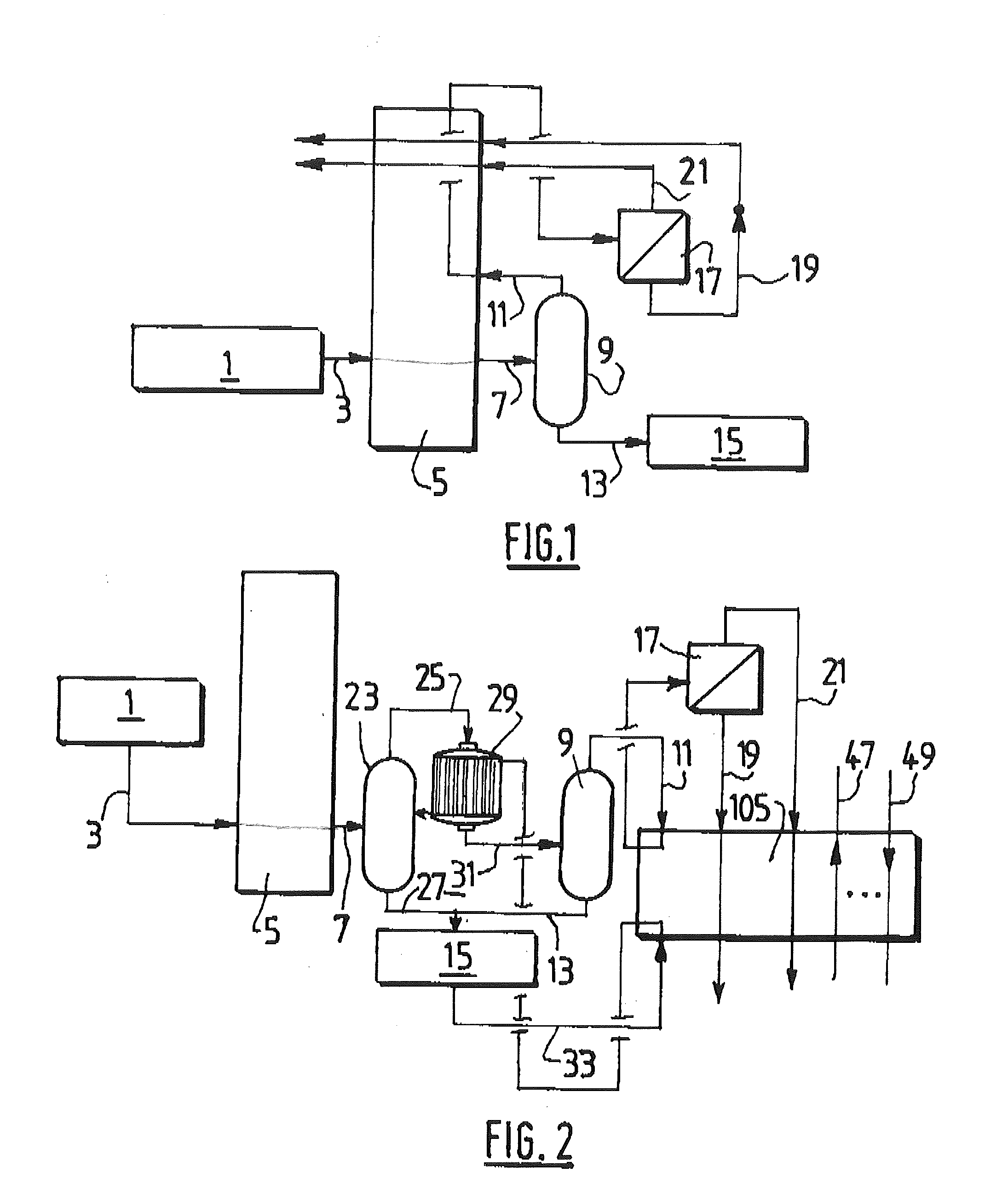
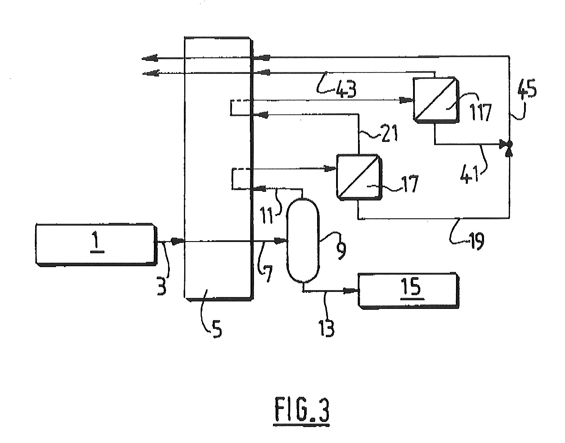
[0041]The invention will be described in greater detail by referring to the figures. FIGS. 1 to 3 represent processes according to the invention.

[0042]In FIG. 1, an oxy-fuel combustion unit 1 produces a gas stream 3 rich in carbon dioxide that contains at least 80% carbon dioxide on a dry basis, and also at least oxygen, nitrogen and argon. The gas is cooled in a first heat exchanger 5 which is a brazed aluminum plate-fin exchanger. The cooled gas 7 at a temperature between −50° C. and −53° C. is sent to a phase separator 9 which produces a gas 11 enriched in oxygen, nitrogen and argon that contains 34% carbon dioxide and a liquid 13 enriched in carbon dioxide. The liquid 13 is sent to a storage vessel 15 as final product. The gas 11 is warmed in the first exchanger 5 to between −35° C. and −45° C., for example −40° C. and then sent to a permeation separation stage 17. This permeation causes a cooling of the products. The permeate 19 at −42° C. is expanded and then sent to be warmed...


PUM


Abstract

A carbon dioxide-rich gas is cooled in a first heat exchanger; the carbon dioxide-rich gas cooled in the first heat exchanger enters a first phase separator at a first temperature between −50° C. and −53° C.; a carbon dioxide-enriched liquid is drawn from the first phase separator and acts as product; a carbon dioxide-depleted gas from the first separator is reheated in the first exchanger to a second temperature between −35° C. and −45° C., without having been expanded downstream from the first phase separator and enters a permeation unit at the second temperature; the reheated gas is subjected to at least one permeation step in the permeation unit in order to produce at least two fluids which are then reheated in the first exchanger, the fluid from the permeation unit, reheated in the exchanger, which exits the permeation unit at the lowest temperature, being at a temperature of more than −54° C.

Description

CROSS REFERENCE TO RELATED APPLICATIONS[0001]This application is a §371 of International PCT Application PCT / FR2013 / 051620, filed Jul. 8, 2013, which claims the benefit of FR1256771, filed Jul. 13, 2012, both of which are herein incorporated by reference in their entireties.TECHNICAL FIELD OF THE INVENTION[0002]The present invention relates to a method for separating a gas rich in carbon dioxide by partial condensation and permeation.BACKGROUND[0003]A gas rich in carbon dioxide contains at least 65 mol %, or at least 80 mol % or even at least 90 mol % of carbon dioxide, on a dry basis.[0004]The gas rich in carbon dioxide contains at least one lighter gas, such as oxygen, nitrogen, carbon monoxide, hydrogen.[0005]Preferably, it contains less than 5 mol % of methane, or even less than 2 mol % of methane.[0006]All the percentages in this document relating to purities are molar percentages.[0007]The low temperature separation of a gas rich in carbon dioxide is particularly chosen as a m...

Claims


Application Information

Patent Timeline
IPC IPC(8): F25J3/06C01B32/50
CPCF25J3/067B01D53/002B01D53/226B01D53/229B01D2257/504B01D2258/0283F25J3/0625F25J3/0223F25J3/0266F25J2200/02F25J2200/70F25J2205/04F25J2205/40F25J2205/80F25J2210/70F25J2215/04F25J2220/82F25J2290/34Y02C20/40
Inventor DAVIDIAN, BENOITLECLERC, MATHIEU
Owner LAIR LIQUIDE SA POUR LETUDE & LEXPLOITATION DES PROCEDES GEORGES CLAUDE
Learn More