An inductive load control circuit, a braking system for a vehicle and a method of measuring current in an inductive load control circuit

a technology of inductive load control and control circuit, which is applied in the direction of process and machine control, pulse technique, instruments, etc., can solve the problems of inability to guarantee redundancy, inconvenient operation, and insufficient circuitry

Inactive Publication Date: 2015-10-22
NXP USA INC
View PDF7 Cites 28 Cited by
  • Summary
  • Abstract
  • Description
  • Claims
  • Application Information

AI Technical Summary

Benefits of technology

[0009]The present invention provides an inductive load control circuit, a braking system for a vehicle and

Problems solved by technology

Detection of a defect in the control circuit may result in disconnection of the associated control unit or switching over to an auxiliary/emergency system.
However, this arrangement does not guarantee redundancy during each PWM period.
Furthermore the diagnostic current measurement is performed by the additional parallel circuit branch rather than by the existing current regulation loop and the additional circuitry is

Method used


Image

  • An inductive load control circuit, a braking system for a vehicle and a method of measuring current in an inductive load control circuit
  • An inductive load control circuit, a braking system for a vehicle and a method of measuring current in an inductive load control circuit
  • An inductive load control circuit, a braking system for a vehicle and a method of measuring current in an inductive load control circuit

Examples


Embodiment Construction

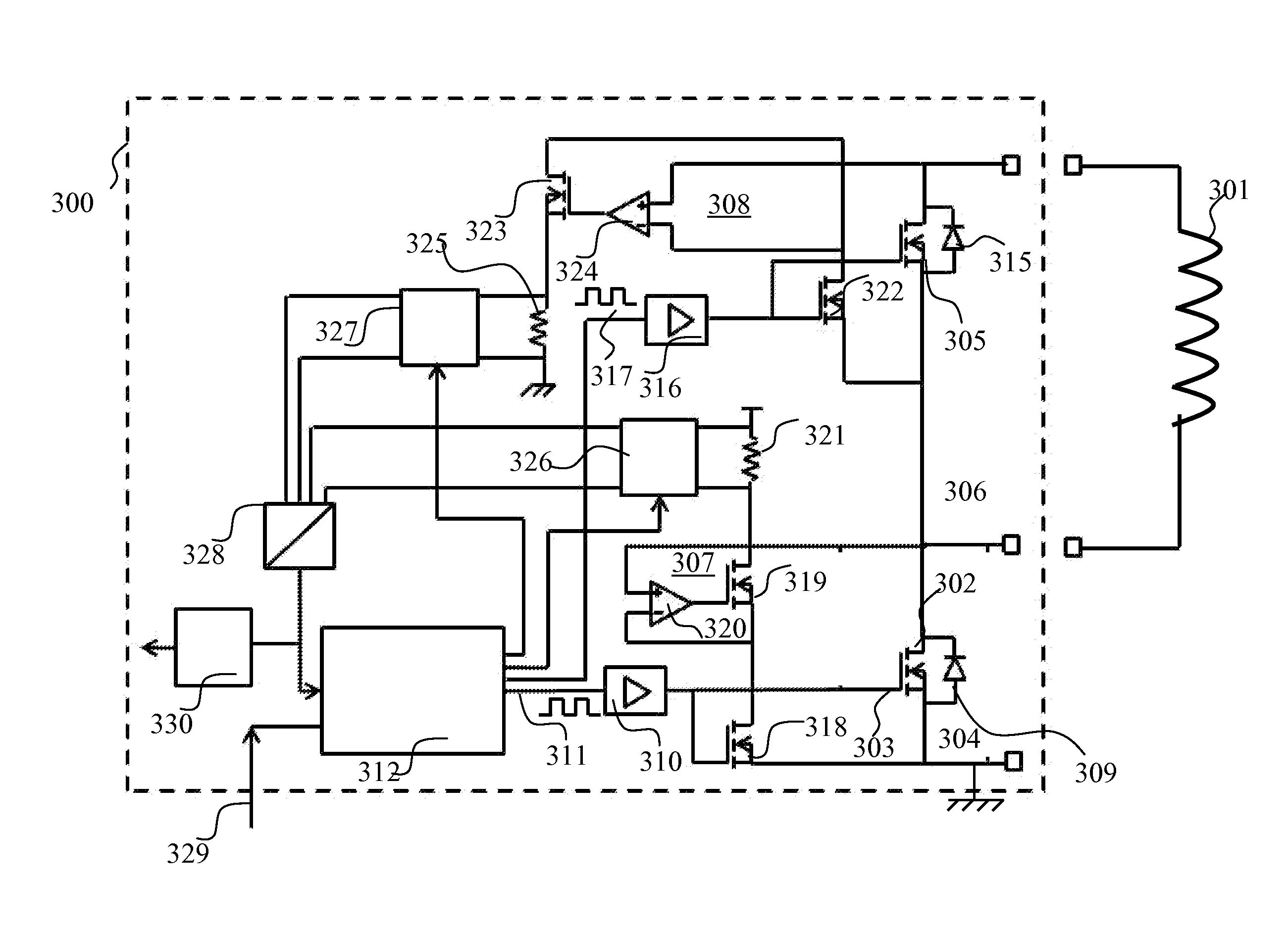
[0018]The present invention will now be described with reference to a load current control circuit 300 illustrated in FIG. 3. Such a circuit may find application in the automotive field for controlling the actuation of an electromechanical valve such as can be found in an anti-lock braking system. A load of this type is an inductive load and represented as a coil 301 in FIG. 3

[0019]Because the illustrated embodiments of the present invention may for the most part, be implemented using electronic components and circuits known to those skilled in the art, details will not be explained in any greater extent than that considered necessary as illustrated, for the understanding and appreciation of the underlying concepts of the present invention and in order not to obfuscate or distract from the teachings of the present invention. Furthermore, it will be appreciated that the present invention is not limited to the specific embodiments illustrated and described herein and in particular, is...


PUM


Abstract

A method and circuit for controlling current through an inductive load such as an electromagnetic valve of a vehicle anti-lock braking system includes first and second driver stages, controlled by PWM (pulse width modulation) signals, for providing, respectively, an actuation path for valve current in an “on” phase and a recirculation path for valve current in an “off” phase. A peak value of current flowing in the actuation path at the end of an “on” phase is compared with a peak value of current flowing in the recirculation path at the start of the “off” phase in order to detect any malfunction of the circuit. An embodiment of the invention has the advantage of being able to detect any malfunction at very low and very high PWM duty cycles.

Description

FIELD OF THE INVENTION[0001]This invention relates to an inductive load control circuit, a braking system for a vehicle and a method for measuring current in such a circuit.BACKGROUND OF THE INVENTION[0002]In an automotive vehicle, electromechanical hydraulic valves (incorporating a solenoid coil) are typically employed in an anti-lock braking system of the vehicle. Such valves may be actuated by electrical control circuits comprising semiconductor components such as power MOSFETs (metal oxide silicon field effect transistor). The valves, and consequently the hydraulic pressure in a braking system, can be controlled using a pulse width modulated driver stage incorporating at least one power MOSFET.[0003]One known valve control circuit is shown in FIG. 1 and indicated generally at 100. A similar arrangement is described in US-A1-20090299592. In FIG. 1 an inductive load 101 (for example the coil of an electromechanical hydraulic valve) is controlled by a high side driver circuit 102 a...

Claims


Application Information

Patent Timeline
IPC IPC(8): H02M3/158B60T8/17G01R31/327G01R17/00G01R31/00
CPCH02M3/158G01R17/00B60T8/17G01R31/327G01R31/006B60T8/885B60T2270/402H03K17/0822H03K17/18H01F7/064H02M3/1555
Inventor FRANCHINI, CHRISTELLEHUOT-MARCHAND, ALEXIS
Owner NXP USA INC
Why Eureka
Try Eureka