Electrical apparatus and method for charging a battery

a technology of electric apparatus and battery, which is applied in the direction of battery/cell propulsion, electric device control, dynamo-electric converter control, etc., can solve the problems of manual connection process, increased need to charge such vehicles, and inability to expect any normal person, etc., and achieves high efficiency

Active Publication Date: 2015-11-05
VOLVO LASTVAGNAR AB
View PDF5 Cites 22 Cited by
  • Summary
  • Abstract
  • Description
  • Claims
  • Application Information

AI Technical Summary

Benefits of technology

[0017]In this method, galvanic isolated charging with high efficiency is obtained by using two separate multi-phase bridge inverters connected

Problems solved by technology

This also means a corresponding increase in the need to charge such vehicles.
The connectors used are strictly standardized but already for 63 A they are so large and cumbersome to handle that one cannot expect any normal person, perhaps wearing good clothing, to manually handle the connecting process.
Since the charging time for these still will be relatively long (typically 30 to 60 minutes), it probably does not make sense to have special charging outlets, since very many of them would be needed as compared to today's petrol stations.
With a rated charging power of up to 400 V, 63 A 3-phase, providing galvanic isolation, a rather heavy (>100 kg, if a 50 Hz transformer is located on board to provide the galvanic isolation) and costly (>10,000 SEK) equipment is needed on board.
Since an electric vehicle is costly already from the outset, especially on account of the costs of the batteries, it is burdened with additional costs for the charger requirement.
A

Method used


Image

  • Electrical apparatus and method for charging a battery
  • Electrical apparatus and method for charging a battery
  • Electrical apparatus and method for charging a battery

Examples


Embodiment Construction

[0022]The embodiments of the invention with further developments described in the following are to be regarded only as examples and are in no way to limit the scope of the protection provided by the patent claims.

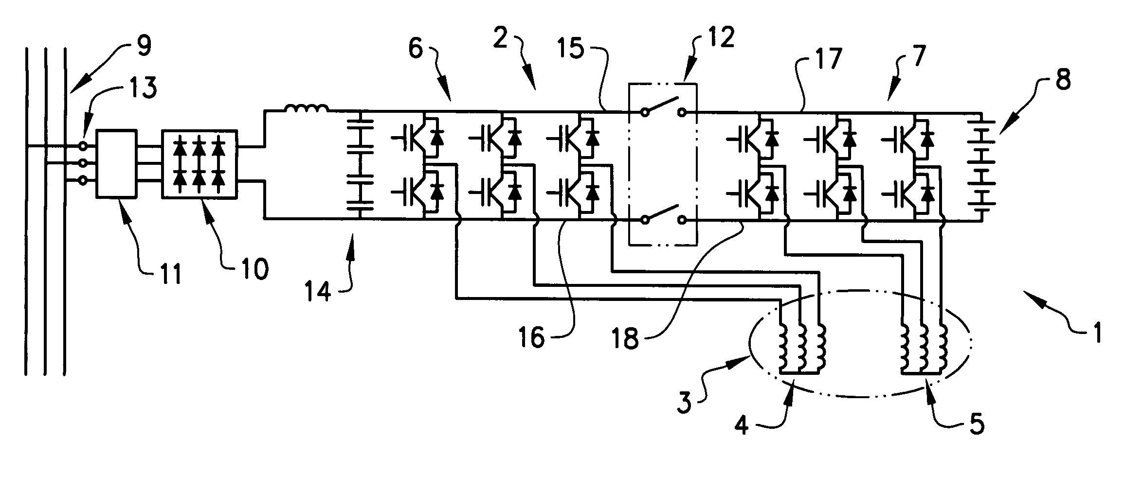
[0023]FIG. 1 shows an electrical apparatus 1 for charging a battery 8. In the described example, the electrical apparatus is integrated in an electrical vehicle and the electrical machine is used as a power source for driving the electrical vehicle when the drive system is in a traction mode. The electrical machine may however also be used for other purposes, e.g. to power different rotational equipment such as hydraulic pumps on construction equipment vehicles. The electrical apparatus 1 comprises an electrical drive system 2 and an electrical machine 3. The electrical drive system is controlled by an electronic control unit in a known manner and is not described further.

[0024]The electrical machine 3 comprises a rotor (not shown) and two separate multi-phase stator windin...


PUM


Abstract

An electrical apparatus is provided including an electrical drive system and an electrical machine. The electrical machine includes a rotor, a first separate multi-phase stator winding and a second separate multi-phase stator winding. The drive system includes a first multi phase bridge inverter connected to the first multi-phase stator winding and which is adapted to be connected to a line voltage supply by a connection means when charging a battery. The apparatus further includes a second multi-phase bridge inverter connected to the second multi-phase stator winding and to the battery. A battery can be charged without the need of a specific charger and charging with galvanic isolation is provided.

Description

BACKGROUND AND SUMMARY[0001]The present invention relates to an electrical apparatus fir charging a battery from a voltage grid and further to a method for charging a battery from a voltage grid. The apparatus is suitable for electric vehicles and other machines comprising an electrical machine.[0002]The share of partly or only electrically driven vehicles is expected to increase radically in the next 10 to 20 years. This also means a corresponding increase in the need to charge such vehicles. In principle, the charging is done by connecting the vehicle to the electrical network, either directly to one of the ordinary outlets used for other equipments, or through a special charger, external to the vehicle. Charging current transferred from the network to a battery on board the vehicle. In the latter case with an external charger, standardization is needed so that vehicles from different manufacturers can all be charged from the same type of outlet.[0003]A passenger car uses around 2...

Claims


Application Information

Patent Timeline
IPC IPC(8): B60L11/18H02P23/00H02J7/02
CPCB60L11/1814B60L11/1803H02P23/0095H02J7/022B60L15/007B60L2210/30B60L2210/40B60L2210/44B60L2220/12B60L2220/14B60L2220/16B60L2220/18B60L2220/54Y02T90/14Y02T10/7072H02P23/28B60L53/14B60L53/22B60L50/51B60L53/24B60L3/0069H02J2310/48H02J7/02H02J2207/20Y02T10/64Y02T10/72Y02T10/70Y02T90/12
Inventor ALAKULA, MATSHOEVENAARS, ERIK
Owner VOLVO LASTVAGNAR AB
Why Eureka
Try Eureka