Image sensor having improved light utilization efficiency

a technology of image sensor and light utilization efficiency, which is applied in the field of image sensor, can solve the problems of color separation element still being unable to provide images, light utilization efficiency may deteriorate, and most light loss in color filters

Active Publication Date: 2015-11-05
SAMSUNG ELECTRONICS CO LTD
View PDF4 Cites 10 Cited by
  • Summary
  • Abstract
  • Description
  • Claims
  • Application Information

AI Technical Summary

Benefits of technology

[0008]According to an aspect, an image sensor includes a first pixel row including a plurality of first pixels configured to sense first wavelength light, the first wavelength light having a first wavelength, a second pixel row adjacent to the first pixel row, the second pixel row including a plurality of second pixels configured to sense second wavelength light and a plurality of third pixels configured to sense third wavelength light, the plurality of second pixels and the plurality of third pixels being alternately arranged, the second wavelength light having a second wavelength and the third wavelength light having a third wavelength, and a plurality of first color separation elements in the plurality of second pixels, respectively, the plurality of separation elements configured to change a spectrum distribution of incident light such that a ratio of the second wavelength light to light incident on the plurality of second pixels and a ratio of the third wavelength light to light incident on the plurality of third pixels increase.

Problems solved by technology

However, a general absorption-type color filter absorbs lights of colors other than its own color, and thus light utilization efficiency may deteriorate.
Therefore, in a color display apparatus or a color image sensor, most light loss occurs in color filters.
However, a color separation element is still unable to provide images that are as clear as images provided by using color filters.

Method used


Image

  • Image sensor having improved light utilization efficiency
  • Image sensor having improved light utilization efficiency
  • Image sensor having improved light utilization efficiency

Examples


Embodiment Construction

[0047]Reference will now be made in detail to embodiments, examples of which are illustrated in the accompanying drawings, wherein like reference numerals refer to like elements throughout. In this regard, the present embodiments may have different forms and should not be construed as being limited to the descriptions set forth herein. Accordingly, the embodiments are merely described below, by referring to the figures, to explain aspects of the present description. It will also be understood that when a layer is referred to as being “on” another layer or substrate, it can be directly on the other layer or substrate, or intervening layers may also be present.

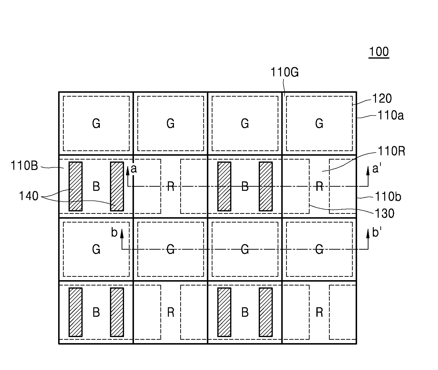
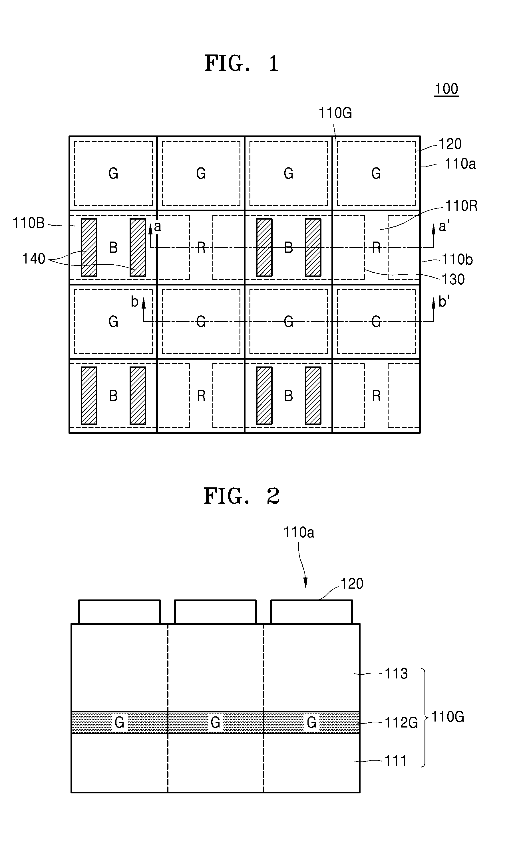
[0048]FIG. 1 is a schematic plan view of a pixel structure of an image sensor 100 according to an embodiment. Referring to FIG. 1, the image sensor 100 may include a pixel array in which a plurality of light detection pixels, that is, red pixels 110R, green pixels 110G, and blue pixels110B are arranged in a two-dimensional matri...


PUM


Abstract

An image sensor includes a first pixel row including a plurality of first pixels configured to sense first wavelength light, the first wavelength light having a first wavelength, a second pixel row adjacent to the first pixel row, the second pixel row including a plurality of second pixels configured to sense second wavelength light and a plurality of third pixels configured to sense third wavelength light, the plurality of second pixels and the plurality of third pixels being alternately arranged, the second wavelength light having a second wavelength and the third wavelength light having a third wavelength and a plurality of first color separation elements in the plurality of second pixels, respectively, the plurality of separation elements configured to change a spectrum distribution of incident light.

Description

RELATED APPLICATIONS[0001]This application claims the benefit of Korean Patent Application No. 10-2014-0052983, filed on Apr. 30, 2014, in the Korean Intellectual Property Office, the disclosure of which is incorporated herein in its entirety by reference.BACKGROUND[0002]1. Field[0003]The present disclosure relates to image sensors, such as image sensors having an improved light utilization efficiency, by using a color separation element and a color filter.[0004]2. Description of the Related Art[0005]A color display apparatus or a color image sensor generally displays images of various colors or detects colors of incident light by using color filters. In a current color display device or a color image sensor, an RGB color filter mechanism is most popularly employed, in which, for example, green filters are arranged at two of four pixels and a blue filter and a red filter are respectively arranged at the other two pixels. Furthermore, other than the RGB color filter mechanism, a CYGM...

Claims


Application Information

Patent Timeline
Patent Type & Authority Applications(United States)
IPC IPC(8): H01L27/146
CPCH01L27/1463H01L27/14627H01L27/14621H01L27/14645H01L27/14623H01L27/14629H01L27/14603H01L31/02162H01L27/14625H01L27/14605
Inventor NAM, SUNGHYUNROH, SOOKYOUNGYUN, SEOKHOSHIN, CHANGGYUNHONG, HYUNGUE
Owner SAMSUNG ELECTRONICS CO LTD
Why Eureka
Try Eureka