Receiving arrangement for a control device in a vehicle, and method for generating a synchronization pulse

a technology of synchronization pulse and control device, which is applied in the direction of pulse technique, data switching network, synchronization signal speed/phase control, etc., can solve the problems of negative and positive voltage offset or positive voltage difference at the end of synchronization puls

Active Publication Date: 2015-11-12
ROBERT BOSCH GMBH
View PDF3 Cites 5 Cited by
  • Summary
  • Abstract
  • Description
  • Claims
  • Application Information

AI Technical Summary

Benefits of technology

[0005]The receiving assemblage according to the present invention for a control device in a vehicle, and the method according to the present invention for generating a synchronization pulse, have the advantage, in contrast thereto, that correct acquisition of the quiescent current by the current sources of the synchronization pulse generator at the start of the synchronization pulse is ensured.
[0007]The essence of the invention is the minimization of inaccuracies in the acquisition of the quiescent current from the voltage supply of the receiver by the charging and discharging current sources in order to generate the synchronization pulse. In addition, embodiments of the present invention assist compliance with limits in accordance with the present PSI5 specification.
[0013]It is particularly advantageous that the voltage generator encompasses at least one digital control application circuit and at least one digital / analog converter, which generate a substantially sinusoidal reference current and output it to the current source and to the current sink. For example, a first digital control application circuit and a first digital / analog converter can generate a substantially sinusoidal reference current and output it to the current source. A second digital control application circuit and a second digital / analog converter can likewise generate a substantially sinusoidal reference current and output it to the current sink. This advantageously makes possible a very robust implementation of the synchronization pulse, and reduced electromagnetic emission. In addition, the application of control to the synchronization pulse can be displaced entirely into the digital section of the circuit, which can result in an area-efficient solution given the constant scaling progress of semiconductor technology. Voltage supply to the receiver can be decoupled from the data bus during the synchronization pulse, while the voltage generator for generating the synchronization pulse is activated. Because the voltage generator for generating the synchronization pulse encompasses a current source and a current sink, the need for an additional switch in series with the current source and the current sink can be eliminated. Alternatively, a shared digital control application circuit and a shared digital / analog converter can generate a substantially sinusoidal reference current and output it to the current source and to the current sink. Shared utilization of the digital control application circuit and of the digital / analog converter can reduce the number of components in the voltage generator and economize on layout area.
[0014]The shape of the synchronization pulse either can be stored in the digital section or in the digital control application circuit, or can be calculated with the aid of an algorithm. The digital / analog converter generates, from an N-bit data word, a reference current that is conveyed via the current source or current sink onto the data bus and respectively charges or discharges the load present on the data bus. In order to generate a substantially sinusoidal synchronization pulse, i.e. a sinusoidal or approximately sinusoidal synchronization pulse, sinusoidal or approximately sinusoidal control is applied both to the current source and to the current sink. For emissions reasons, the resolution of the data word can be selected in such a way that the synchronization pulse can be mapped without significant discontinuities. The capacitance of the bus load integrates the bus current and thereby smooths the voltage on the data bus.

Problems solved by technology

For example, if the charging current from the voltage generator is greater than the quiescent current of the residual receiver circuit, this can result in a positive voltage offset or a positive voltage difference at the end of the synchronization pulse.
If the charging current from the voltage generator is less than the quiescent current, this can result in a negative voltage offset or a negative voltage difference at the end of the synchronization pulse.

Method used


Image

  • Receiving arrangement for a control device in a vehicle, and method for generating a synchronization pulse
  • Receiving arrangement for a control device in a vehicle, and method for generating a synchronization pulse
  • Receiving arrangement for a control device in a vehicle, and method for generating a synchronization pulse

Examples


Embodiment Construction

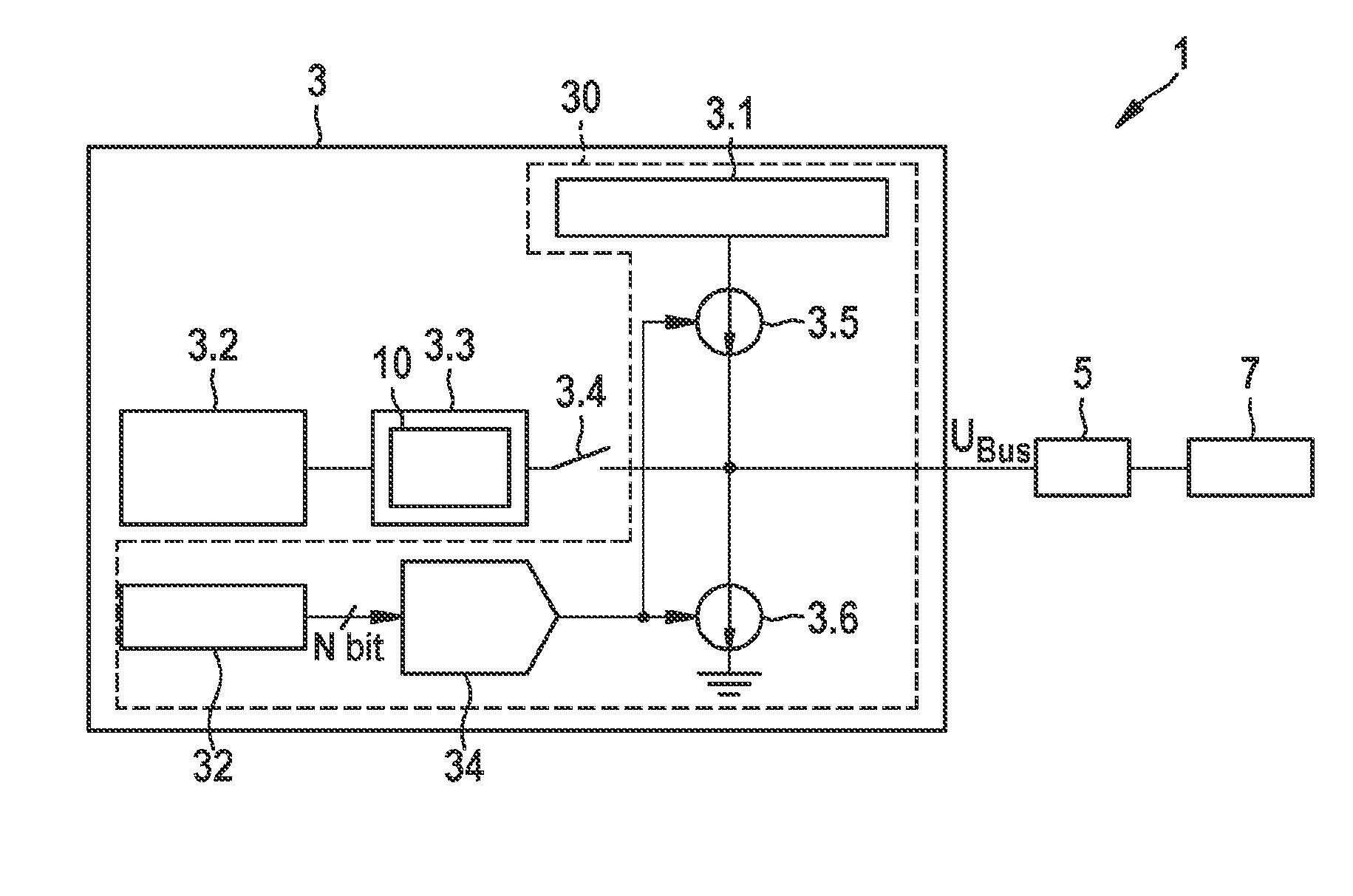
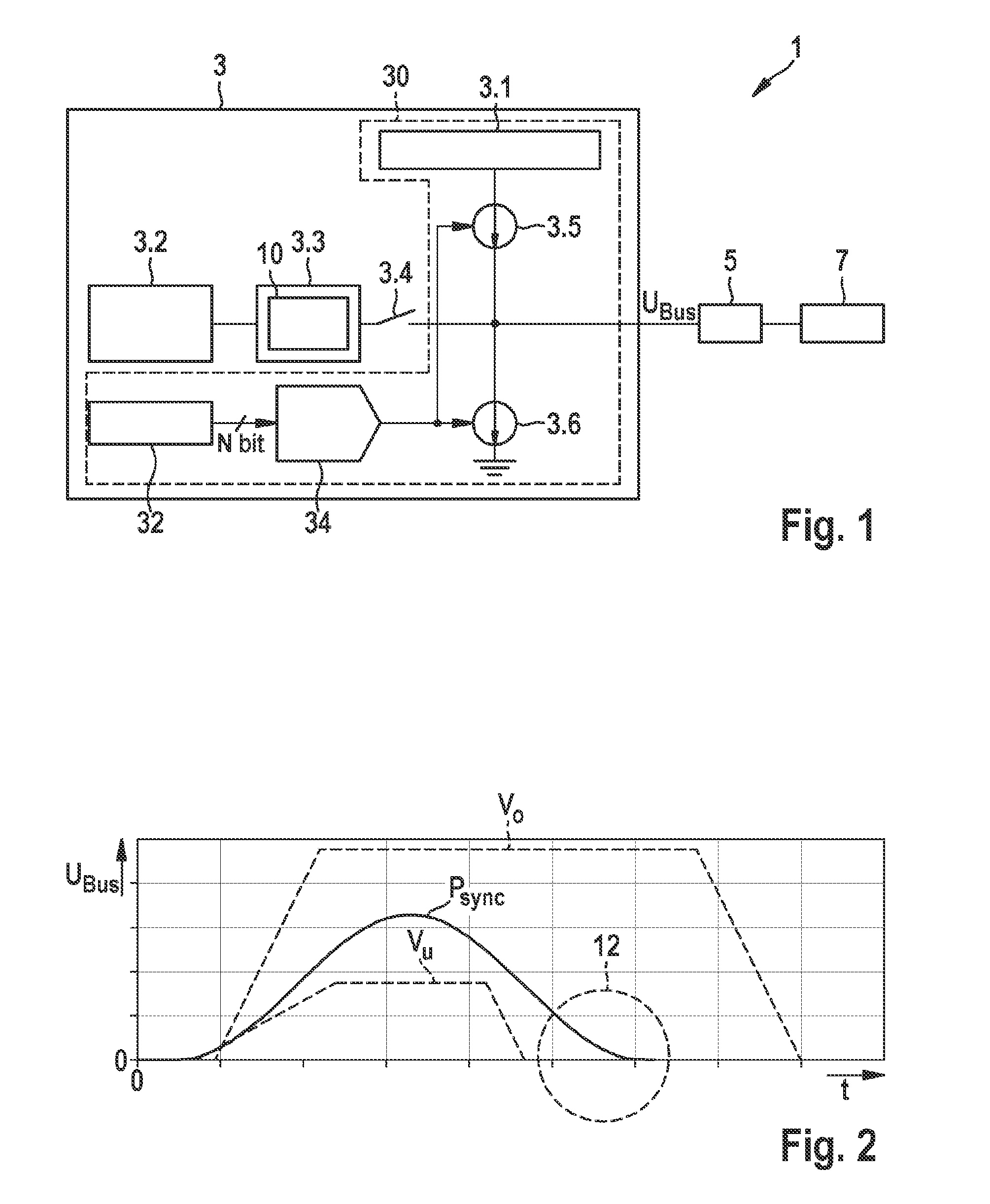
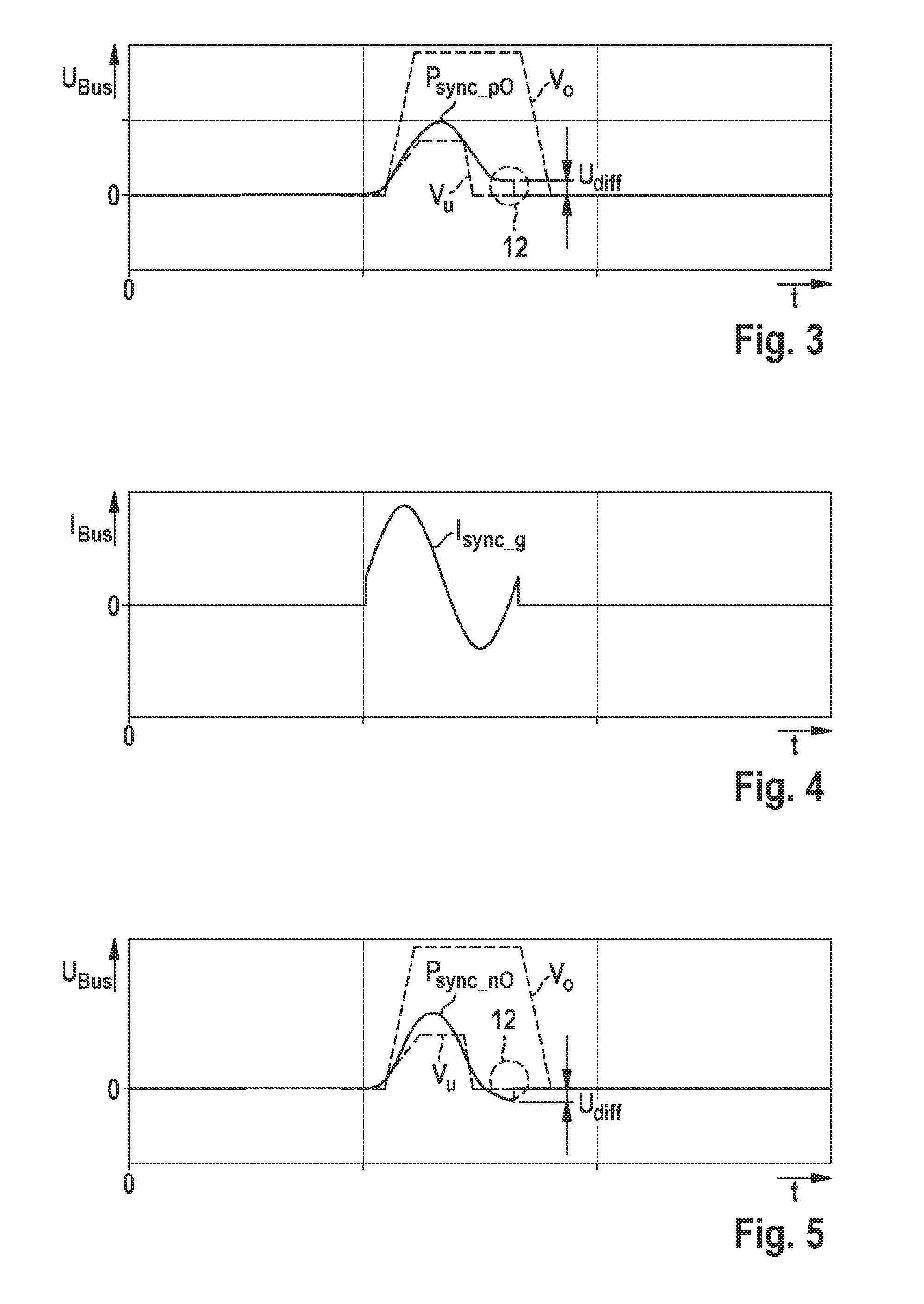
[0024]As is evident from FIG. 1, the exemplifying embodiment depicted of a sensor assemblage 1 encompasses a data bus 5, at least one sensor 7, and an exemplifying embodiment of a receiving assemblage 3 according to the present invention for a control device in a vehicle. Receiving assemblage 3 according to the present invention encompasses a voltage generator 30 for generating a synchronization pulse Psync, having a first voltage source 3.1, a current source 3.5, and a current sink 3.6. Voltage generator 30 generates the synchronization pulse Psync by way of current source 3.5 and current sink 3.6, substantially as a sinusoidal oscillation, by charging and / or discharging a bus load. Receiving assemblage 3 outputs the synchronization pulse Psync via data bus 5 to the at least one sensor 7 for synchronization of a subsequent signal transfer. According to the present invention, voltage generator 30 compares a voltage value at the end 12 of the synchronization pulse Psync with a corres...


PUM


Abstract

A receiving assemblage is provided for a control device in a vehicle, having a voltage generator for generating a synchronization pulse, which encompasses a first voltage source, a current source, and a current sink, the voltage generator generating the synchronization pulse within predefined specification limits with a predefined shape and a predefined time-related behavior, and the receiving assemblage outputting the synchronization pulse via a data bus to at least one sensor for synchronization of a subsequent signal transfer, the voltage generator generating the synchronization pulse via the current source and the current sink, substantially as a sinusoidal oscillation, by charging and / or discharging a bus load, and to a method for generating a synchronization pulse.

Description

FIELD OF THE INVENTION[0001]The present invention proceeds from a receiving assemblage for a control device in a vehicle, and from an associated method for generating a synchronization pulse.BACKGROUND INFORMATION[0002]Peripheral sensors for occupant protection systems usually use current interfaces (e.g. PAS4, PSI5) to transfer sensor data to a central control device (ECU) in a vehicle. In current interfaces of the latest generation (PSI5), bus operation with multiple sensors on one receiver is made possible by synchronization. For the synchronization function, a working clock signal in the form of a voltage pulse is generated by the central control device (ECU); said pulse is detected by the sensors on the bus and characterizes the beginning of a new cycle for data transfer. This voltage pulse is referred to as a “synchronization pulse” and is produced with the aid of current sources and current sinks that respectively charge and discharge the bus load. This voltage pulse is typic...

Claims


Application Information

Patent Timeline
Patent Type & Authority Applications(United States)
IPC IPC(8): B60R16/03B60R16/023
CPCB60R16/023B60R16/03H03K4/94H04L7/0091H04L7/044H04L7/06H04L12/40006
Inventor SIEMSS, MATTHIASMOMENI, MASSOUD
Owner ROBERT BOSCH GMBH
Why Eureka
Try Eureka