
Cycloidal marine-propulsion system

a technology of cycloidal propellers and propeller blades, which is applied in marine propulsion, machine/engines, and ships. it can solve the problems of slowing down the vehicle, affecting the speed of the vehicle, and the vertical propeller blades of the cycloidal drive create undetectable high drag in the water, so as to reduce the drag. the effect of significan

Inactive Publication Date: 2015-11-12
GE ENERGY POWER CONVERSION TECH
View PDF9 Cites 19 Cited by
  • Summary
  • Abstract
  • Description
  • Claims
  • Application Information

AI Technical Summary

Benefits of technology

The patent describes a system for reducing drag and increasing efficiency in marine propulsion. It uses multiple electric drives that are connected to cycloidal propeller blades, allowing for complex and fine control of blade position and movement. The system can create, increase, or re-direct thrust, and also improves response time between desired blade action. The individual blade control promotes efficiency and fine control, and a direct electric drive further promotes quick response time and is linked to the main system axis shaft and disc or plate holding the propeller blades.

Problems solved by technology

The drive provides input power and torque for a relatively complex group of intermediary structures leading to a complex mechanical gearbox and crosshead arrangement.
During vessel movement, and especially high-vessel-speed operation, the vertical propeller blades of a cycloidal drive create undesirably high drag in the water.
The drag is particularly high under certain conditions, such as during continuous running of the vessel at high power.
The drag slows the vehicle, limiting speed and thus vessel efficiency.
The drag also lowers fuel economy, requiring more power and so fuel to overcome the drag.
Due to the relatively complex intermediate structures, mechanical gearbox, and crosshead arrangement described, response time between a triggering input—e.g., a signal transmitted in response to a captain pulling a lever—and the desired response is also undesirably high.
The complex mechanical drive is also noisy and causes unwanted vibration due to unbalanced forces and couples.

Method used


Image

  • Cycloidal marine-propulsion system
  • Cycloidal marine-propulsion system
  • Cycloidal marine-propulsion system

Examples


Embodiment Construction

[0024]While exemplary embodiments are described herein with illustrative embodiments for particular implementations, it should be understood that the technology is not limited thereto. Those skilled in the art with access to the teachings provided herein will recognize additional modifications, applications, and embodiments within the scope thereof, and additional fields in which the cycloidal marine-propulsion system described herein would be of significant utility.

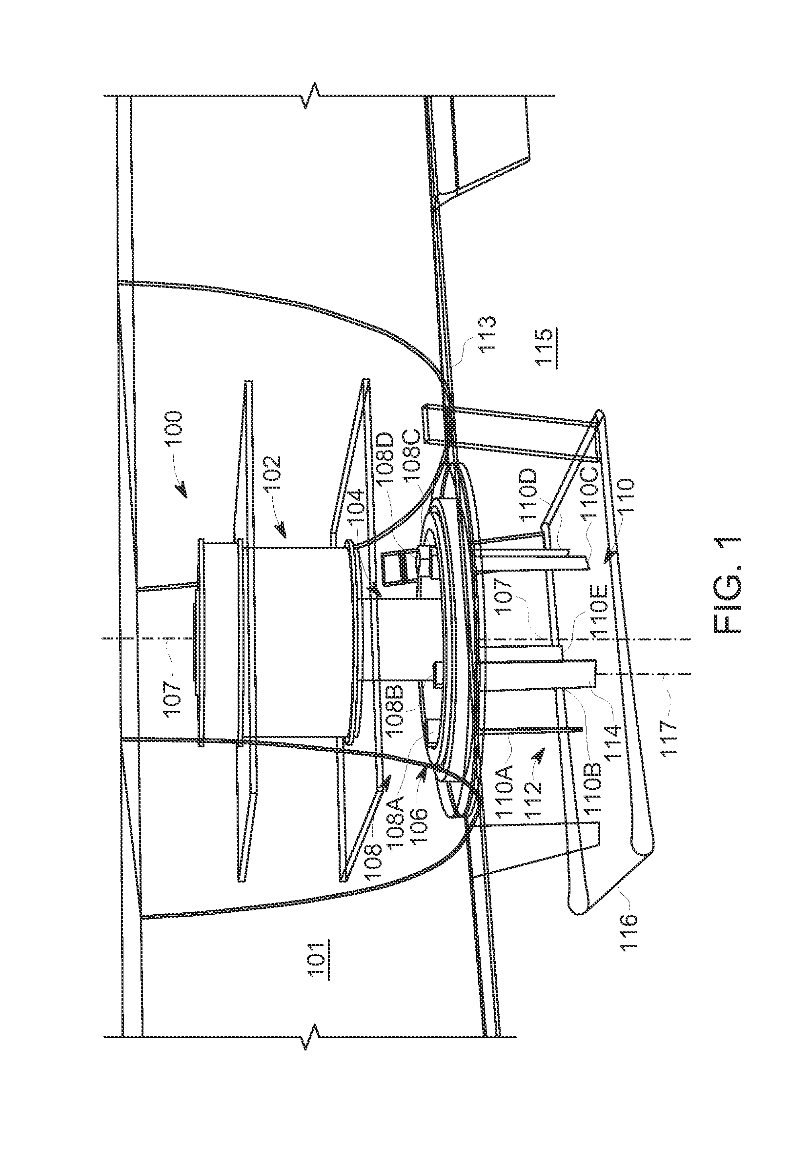
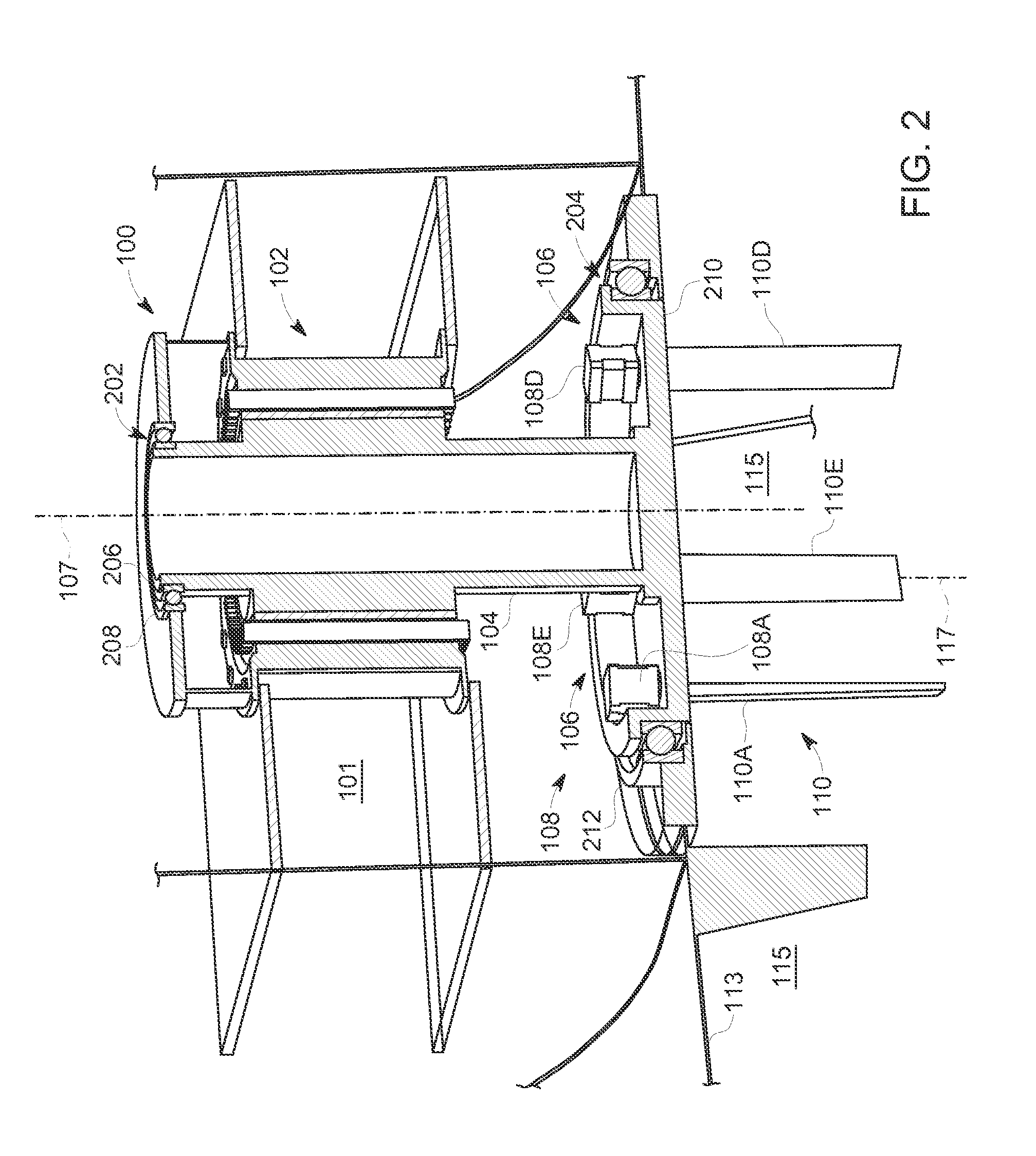
[0025]FIG. 1—System Components

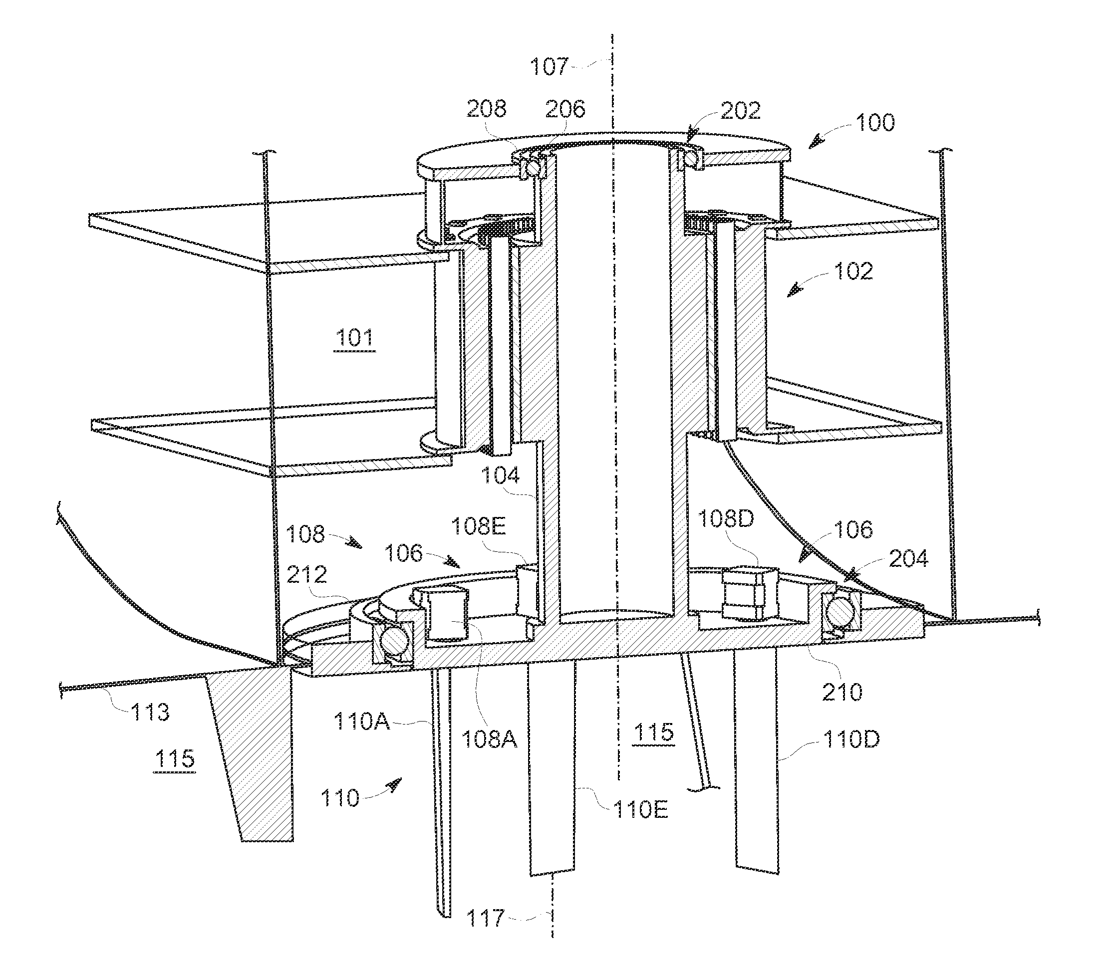
[0026]FIG. 1 is a perspective view of a cycloidal marine propulsion system 100, positioned in a marine vessel 101, according to embodiments of the present technology. The system 100 includes a primary drive 102.

[0027]In one embodiment, the primary drive 102 is a fully electric drive.

[0028]The drive 102 is in one embodiment linked directly (e.g., without complex intermediary components such as clutches, step down or up gears) to a main vertical system shaft 104 of the system 100. The drive 10...


PUM


Abstract

A cycloidal marine-propulsion system is disclosed. The system comprises a blade-mounting disc and a plurality of propeller blades. Each of the plurality of propeller blades has a respective primary blade axis and is connected to the disc in a manner allowing the blade to be rotated about its primary blade axis independent of any about-axis rotation of every other one of the propeller blades. The system also includes a plurality of electric actuators, each actuator being connected to a respective one of the propeller blades. The system further includes a controller in communication with the electric actuators for controlling selectively each of the electric actuators.

Description

TECHNICAL FIELD[0001]The present technology relates generally to a cycloidal-marine propulsion system. In some embodiments, the technology relates more particularly to a cycloidal marine-propulsion system comprising multiple electric motors for controlling individually each of multiple respective cycloidal blades.BACKGROUND OF THE INVENTION[0002]A cycloidal-drive propeller system is a specialized marine propulsion system allowing high maneuverability. The system allows change of vessel thrust to a direction and magnitude per command.[0003]Cycloidal-drive propeller systems are used widely in vessels for which station keeping and high maneuverability at lower speeds are central functions, such as tugboats, ferries, and offshore support vehicles. A conventional type of cycloidal-drive propeller system is a Voith-Schneider propeller (VSP) system.[0004]Conventional cycloidal propeller systems use heavy-duty drive engines such as a diesel motor drive. The drive provides input power and to...

Claims


Application Information

Patent Timeline
IPC IPC(8): B63H3/06B63H3/00
CPCB63H3/002B63H3/06B63H1/10B63H2001/105
Inventor BRADLEY, STUARTURZON, ARKADIUSZ JANUSZ
Owner GE ENERGY POWER CONVERSION TECH
Learn More