Exhaust Gas Processing System Independent to Engine Controls

a processing system and exhaust gas technology, applied in the direction of engines, machines/engines, mechanical equipment, etc., can solve the problems of deteriorating control performance and diagnosis capabilities, inability to effectively remove oxidative specie nox, and limited application

Active Publication Date: 2015-11-12
QI BAOHUA
View PDF6 Cites 19 Cited by
  • Summary
  • Abstract
  • Description
  • Claims
  • Application Information

AI Technical Summary

Benefits of technology

[0011]The present invention provides a multi-functional apparatus and method for diagnosing issues in an internal combustion engine system with a SCR system and controlling reductant delivery to the SCR system. More specifically, this apparatus includes a Venturi exhaust passage device which has an upstream high pressure passage, a low pressure passage, and a downstream high pressure passage. The upstream and downstream high pressure passages have their cross-section area larger than that of the low pressure passage. A temperature sensor is positioned on the upstream high pressure passage, while an absolute pressure sensor is used for measuring an exhaust gas pressure in the upstream high pressure passage. The difference between the exhaust gas pressure in the upstream high pressure passage and an exhaust gas pressure in the low pressure passage is measured with a differential pressure sensor, and a reductant injection device is posit...

Problems solved by technology

In lean combustion engines, due to the effects of large amount oxygen excess, passive means without extra dosing agents, such as that using a three-way catalyst, normally are not able to effectively remove the oxidative specie NOx, as that in most of spark-ignition engines.
However, due to safety concerns and difficulties in handling pure ammonia, normally urea solution, which is also called reductant, is used in ammonia SCR systems.
However, the engine operating parameter values are not alwa...

Method used


Image

  • Exhaust Gas Processing System Independent to Engine Controls
  • Exhaust Gas Processing System Independent to Engine Controls
  • Exhaust Gas Processing System Independent to Engine Controls

Examples


Embodiment Construction

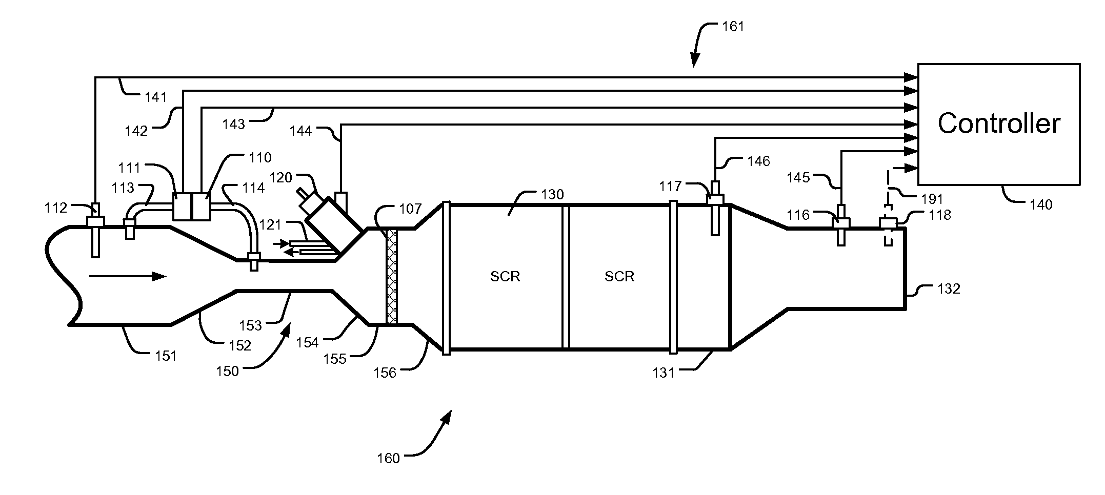
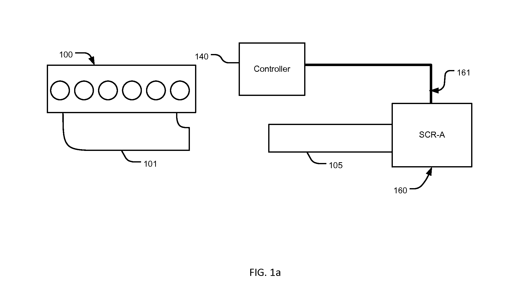
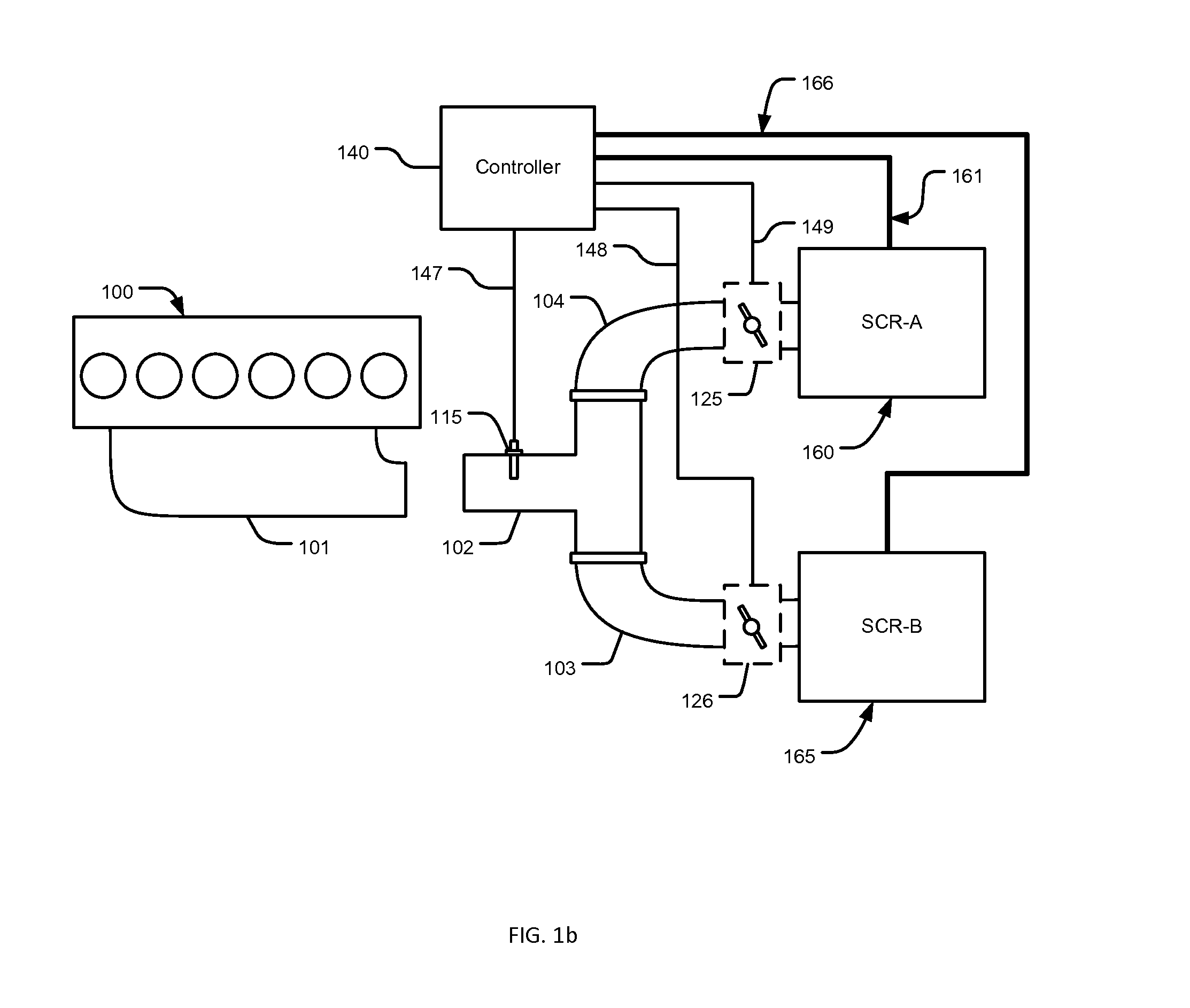
[0024]Referring to FIG. 1a, an engine 100 has a manifold 101. In a single branch system, exhaust gas produced by the engine 100 flows through the manifold 101 into an exhaust passage 105, entering a SCR device 160 controlled by a controller 140 through signal lines 161. In the SCR device 160, NOx in the exhaust gas is reduced. In a multi-branch system, referring to FIG. 1b, the exhaust gas generated by the engine 100 enters a splitting passage 102, at the inlet of which a NOx sensor 115 is installed in communication with the controller 140 through signal lines 147. A first exhaust passage 104 fluidly connects the splitting passage 102 to the SCR device 160, and a control valve 125, which is controlled by the controller 140 through signal lines 149, is used for controlling exhaust flow in the passage 104. In addition to the SCR device 160, a second SCR device 165 is fluidly connected to the splitting passage 102 through an exhaust passage 103. And a control valve 126 controlled by th...


PUM


Abstract

A multi-functional apparatus and method for diagnosing issues in an engine system with a SCR exhaust gas processing system and controlling reductant delivery to the SCR system. The apparatus includes a Venturi exhaust passage device with a reductant injector positioned on a transition from a low pressure passage to a downstream high pressure passage. Temperature and pressures in the Venturi exhaust passage device are measured, and an exhaust flow rate value is calculated. The exhaust flow rate value can be used in controlling reductant delivery, and with a downstream lambda sensing value, the exhaust flow rate value, and a temperature sensing value, a variety of issues in the engine system and the SCR system can be detected. No engine operating parameter is required in the SCR controls and diagnostic algorithms, and less reductant deposit is introduced due to the elimination of stagnant area in the exhaust passage device.

Description

[0001]This present application claims priority from U.S. provisional application No. 61 / 989,364 having the same title as the present invention and filed on May 6, 2014.TECHNICAL FIELD OF THE INVENTION[0002]This invention relates to an apparatus and method for diagnosing issues in an internal combustion engine system with an exhaust gas processing system for removing regulated species, and controlling the exhaust gas processing system, more specifically, to an apparatus and method for diagnosing issues in an internal combustion engine system with a SCR (Selective Catalytic Reduction) system and controlling reductant delivery to the SCR system.BACKGROUND OF THE INVENTION[0003]Environmentally harmful species in the exhaust gas emitted from an internal combustion engine, such as hydrocarbons (HC), carbon monoxide (CO), particulate matters (PM), and nitric oxides (NOx) are regulated species that need to be removed from the exhaust gas. In lean combustion engines, due to the effects of la...

Claims


Application Information

Patent Timeline
IPC IPC(8): F01N3/20F01N11/00F01N9/00
CPCF01N3/208F01N11/00F01N9/00F01N2470/30F01N2550/05F01N2560/06F01N2560/08F01N2610/02F01N2610/1453F01N2900/1404F01N2900/1406F01N2900/1812F01N13/0093F01N13/011Y02T10/12Y02T10/40
Inventor QI, BAOHUA
Owner QI BAOHUA
Why Eureka
Try Eureka