Complex three-dimensional multi-layer structure and manufacturing method thereof

a three-dimensional multi-layer structure and complex technology, applied in the direction of planar/plate-like light guides, instruments, other domestic objects, etc., can solve the problems of large number of optical sheets used in displays, and large technical problems, so as to simplify the production of multi-layer fine ciliary structures

Inactive Publication Date: 2015-11-12
MINUTA TECH CO LTD
View PDF3 Cites 10 Cited by
  • Summary
  • Abstract
  • Description
  • Claims
  • Application Information

AI Technical Summary

Benefits of technology

[0053]In contrast, the method of the present invention enables the production of a multilayer fine ciliary structure consisting of two or more layers by one-time processing. The method of the present invention greatly simplifies the production of a multilayer fine ciliary structure compared to t

Problems solved by technology

Thus, backlight assemblies as separate devices for irradiating light onto liquid display panels are inevitably required in liquid crystal displays.
The light guide plate or the diffusion plate suffers from the disadvantage of very low exit angle or front luminance, which increases the number of the optical sheets stacked thereon.
As described above, optical sheets used in displays are large in number and are expensive.
Thus, a reduction in the number of optical sheets use

Method used


Image

  • Complex three-dimensional multi-layer structure and manufacturing method thereof
  • Complex three-dimensional multi-layer structure and manufacturing method thereof
  • Complex three-dimensional multi-layer structure and manufacturing method thereof

Examples


embodiments

[0083]Hereinafter, a description will be given concerning embodiments of the present invention.

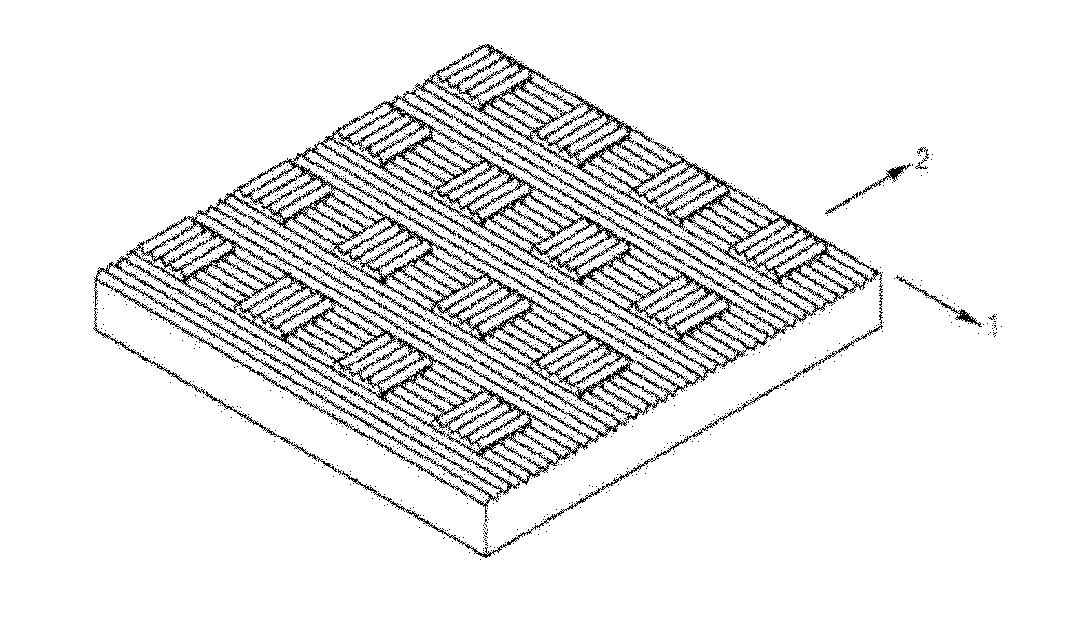
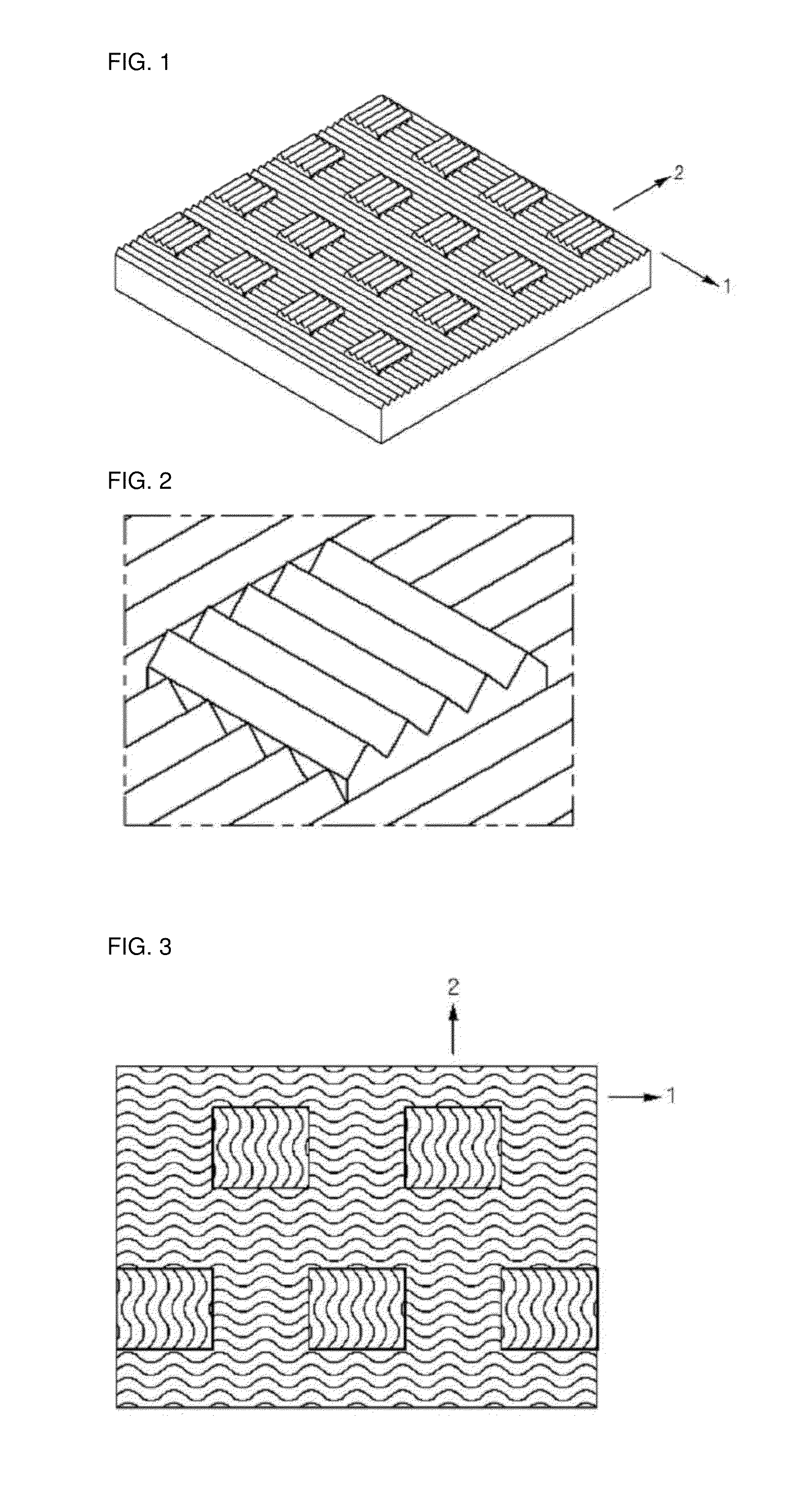
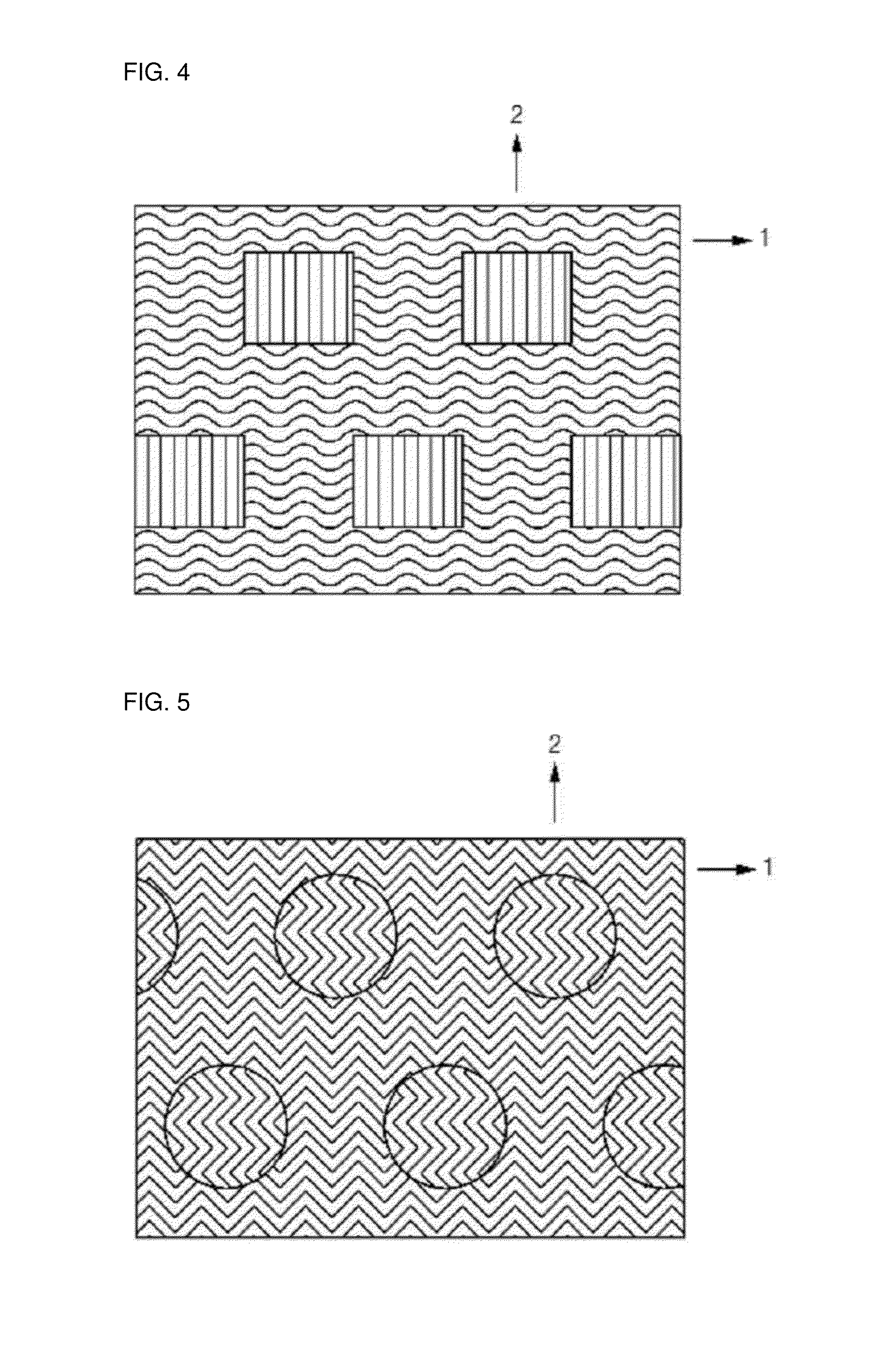
[0084]The present invention provides a 3-dimensional complex multilayer structure including a first pattern, a second pattern, and optionally a third pattern wherein the first and second patterns are formed on one surface of a plate and have different thicknesses, the first pattern is selected from the group consisting of parallel lines, parallel curves, parallel zigzag lines, and combinations thereof which do not meet each other, the second pattern is not parallel to the first pattern and is selected from the group consisting of parallel lines, parallel curves, parallel zigzag lines, and combinations thereof which do not meet each other, the interfaces between the first pattern and the second pattern form figures selected from the group consisting of polygons, circles, ellipses, and combinations thereof, and the figures are repetitively formed on one surface of the plate.

[0085]The two or ...


PUM

PropertyMeasurementUnit
Angleaaaaaaaaaa
Lengthaaaaaaaaaa
Heightaaaaaaaaaa

Abstract

The present invention relates to a 3-dimensional complex multilayer structure. The 3-dimensional complex multilayer structure includes a first pattern and a second pattern having different thicknesses formed on one or both surfaces of a plate. The first pattern is selected from the group consisting of parallel lines, parallel curves, parallel zigzag lines, and combinations thereof which do not meet each other. The second pattern is not parallel to the first pattern and is selected from the group consisting of parallel lines, parallel curves, parallel zigzag lines, and combinations thereof which do not meet each other. The interfaces between the first pattern and the second pattern form figures selected from the group consisting of polygons, circles, ellipses, and combinations thereof. The figures are repetitively formed on one or both surfaces of the plate. The 3-dimensional complex multilayer structure includes different complex patterns, whereas a conventional device has a kind of simple pattern. The 3-dimensional complex multilayer structure of the present invention can be manufactured by a simple process. Therefore, the 3-dimensional complex multilayer structure of the present invention can find application in various fields, including optical components for displays (e.g., light guide plates, diffusion plates, prisms, and color filters), next generation displays and display devices (e.g., TFTs, OTFTs, oxide TFTs, flexible displays, and transparent displays), next generation 3-dimensional semiconductors, dry adhesion based on the use of fine ciliary structures, micro/nano piezoelectric devices, lighting optical components, and biocell/virus research using micropatterns.

Description

BACKGROUND OF THE INVENTION[0001]1. Field of the Invention[0002]The present invention relates to a 3-dimensional complex multilayer structure. More specifically, the present invention relates to a 3-dimensional complex multilayer structure having a complex shape that can be used in a wide variety of fields, including optics, measuring instruments, integrated circuits, and other microdevices, and a method for manufacturing the multilayer structure.[0003]2. Description of the Related Art[0004]With the recent technological developments in the fields of optics, measuring instruments, integrated circuits, and other microdevices, a great deal of research has been conducted on micro / nano-sized structures having complex 3-dimensional shapes that can find application in various fields, including optical components, next generation 3-dimensional semiconductors, next generation displays (such as TFT backplanes, flexible TFTs, and transparent displays), dry adhesion based on the use of fine cil...

Claims


Application Information

Patent Timeline
IPC IPC(8): G02B5/04B29C59/16F21V8/00
CPCG02B5/04G02B6/0058Y10T428/2457B29D11/00865B29L2011/00B29C59/16G02B5/0231G02B5/0257G02B5/0263G02B5/0268G02B5/045G02B6/0025G02B6/0016G02B6/0053G02B6/0036B32B3/30Y10T428/24612Y10T428/24479Y10T428/24174G02B6/00G02B5/02G02B5/20G02B6/12
Inventor LIM, HAN EOLCHOI, SE JINKIM, TAE WANBAEK, SEUNG JOON
Owner MINUTA TECH CO LTD
Why Eureka
Try Eureka