
Mask-less fabrication of vertical thin film batteries

a technology of vertical thin film and fabrication process, which is applied in the direction of secondary cell manufacturing, sustainable manufacturing/processing, final product manufacturing, etc., can solve the problems of capital investment, significant complexity and cost associated with using shadow masking processes in hvm, and still need to be overcome, so as to simplify the tfb manufacturing process and increase substrate utilization and yield.

Inactive Publication Date: 2015-11-12
APPLIED MATERIALS INC
View PDF2 Cites 38 Cited by
  • Summary
  • Abstract
  • Description
  • Claims
  • Application Information

AI Technical Summary

Benefits of technology

This patent describes a new type of battery that has a unique structure and is more efficient and cost-effective to manufacture. The battery uses a vertical structure, with the anode and cathode connected at the top and bottom of the battery, which increases substrate utilization and yield. The manufacturing process is simplified as the layers are deposited without the need for a mask, which reduces costs and improves the performance of the battery. The vertical structure, blanket deposition, and ex-situ laser patterning improve pattern accuracy, yield, and device performance. The new battery has the potential to become more widespread and affordable.

Problems solved by technology

However, there are challenges that still need to be overcome to allow cost effect high volume manufacturing (HVM) of TFBs.
There is significant complexity and cost associated with using shadow mask processes in HVM: (1) a significant capital investment is required in equipment for managing, precision aligning and cleaning the masks, especially for large area substrates; (2) there is poor utilization of substrate area due to having to accommodate deposition under shadow mask edges and limited alignment accuracy; and (3) there are constraints on the PVD processes—low power and temperature—in order to avoid thermal expansion induced alignment issues.
In HVM processes, the use of shadow masks (ubiquitous for traditional and current state-of-the-art TFB fabrication technologies) will contribute to higher complexity and higher cost in manufacturing.
The complexity and cost result from the required fabrication of highly accurate masks and (automated) management systems for mask alignment and regeneration.
In addition, the cost results from the need for maintaining the masks as well as from throughput limitations by the added alignment steps.
The adaptation becomes increasingly more difficult and costly as the manufacturing is scaled to larger area substrates for improved throughput and economies of scale (i.e., HVM).
Moreover, the scaling (to larger substrates) itself can be limited because of the limited availability and capability of shadow masks.
Another impact of the use of shadow masking is the reduced utilization of a given substrate area, leading to non-optimal battery densities (charge, energy and power).
In addition, there are the inherent alignment limitations that come from inaccuracies in mask fabrication and alignment accuracies of an alignment tool.
The consequence of this minimum non-overlap requirement is the loss of cathode area, leading to overall loss of capacity, energy and power content of the TFB (when everything else is the same).
A further impact of shadow masks is limited process throughput due to having to avoid additional thermally induced alignment problems—thermal expansion of the masks leads to mask warping and shifting of mask edges away from their aligned positions relative to the substrate.
Furthermore, processes that employ physical (shadow) masks typically suffer from particulate contamination, which ultimately impacts the yield.

Method used


Image

  • Mask-less fabrication of vertical thin film batteries
  • Mask-less fabrication of vertical thin film batteries
  • Mask-less fabrication of vertical thin film batteries

Examples


Embodiment Construction

[0027]Embodiments of the present invention will now be described in detail with reference to the drawings, which are provided as illustrative examples of the invention so as to enable those skilled in the art to practice the invention. The drawings provided herein are merely representations of devices and device process flows and are not drawn to scale. Notably, the figures and examples below are not meant to limit the scope of the present invention to a single embodiment, but other embodiments are possible by way of interchange of some or all of the described or illustrated elements. Moreover, where certain elements of the present invention can be partially or fully implemented using known components, only those portions of such known components that are necessary for an understanding of the present invention will be described, and detailed descriptions of other portions of such known components will be omitted so as not to obscure the invention. In the present specification, an em...


PUM

PropertyMeasurementUnit
Thicknessaaaaaaaaaa
Electrical conductivityaaaaaaaaaa
Electrical conductoraaaaaaaaaa

Abstract

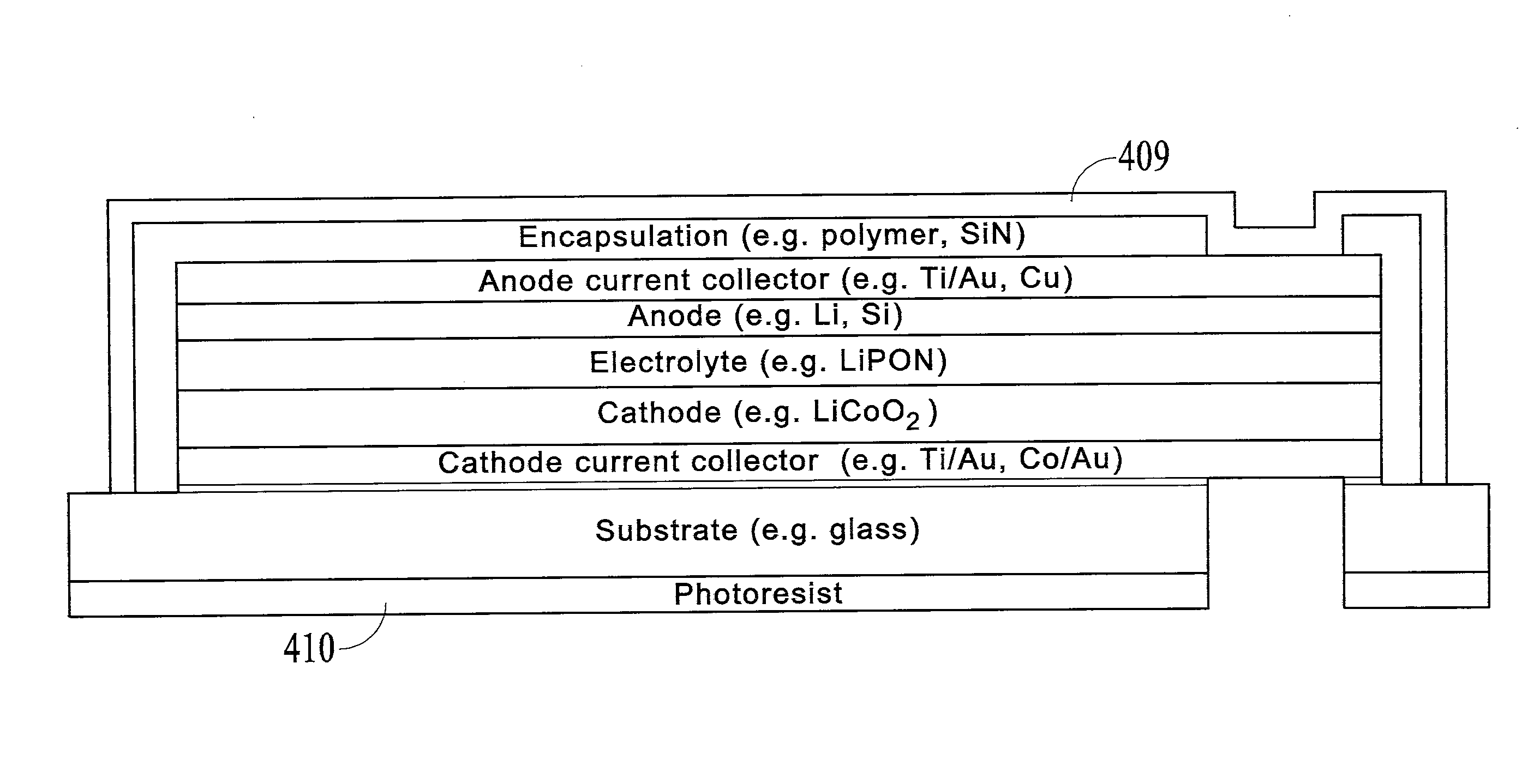
A method of fabricating a thin film battery may comprise: depositing a first stack of blanket layers on a substrate, the first stack comprising a cathode current collector, a cathode, an electrolyte, an anode and an anode current collector; laser die patterning the first stack to form one or more second stacks, each second stack forming the core of a separate thin film battery; blanket depositing an encapsulation layer over the one or more second stacks; laser patterning the encapsulation layer to open up contact areas to the anode current collectors on each of the one or more second stacks; blanket depositing a metal pad layer over the encapsulation layer and the contact areas; and laser patterning the metal pad layer to electrically isolate the anode current collectors of each of the one or more thin film batteries. For electrically non-conductive substrates, cathode contact areas are opened-up through the substrate.

Description

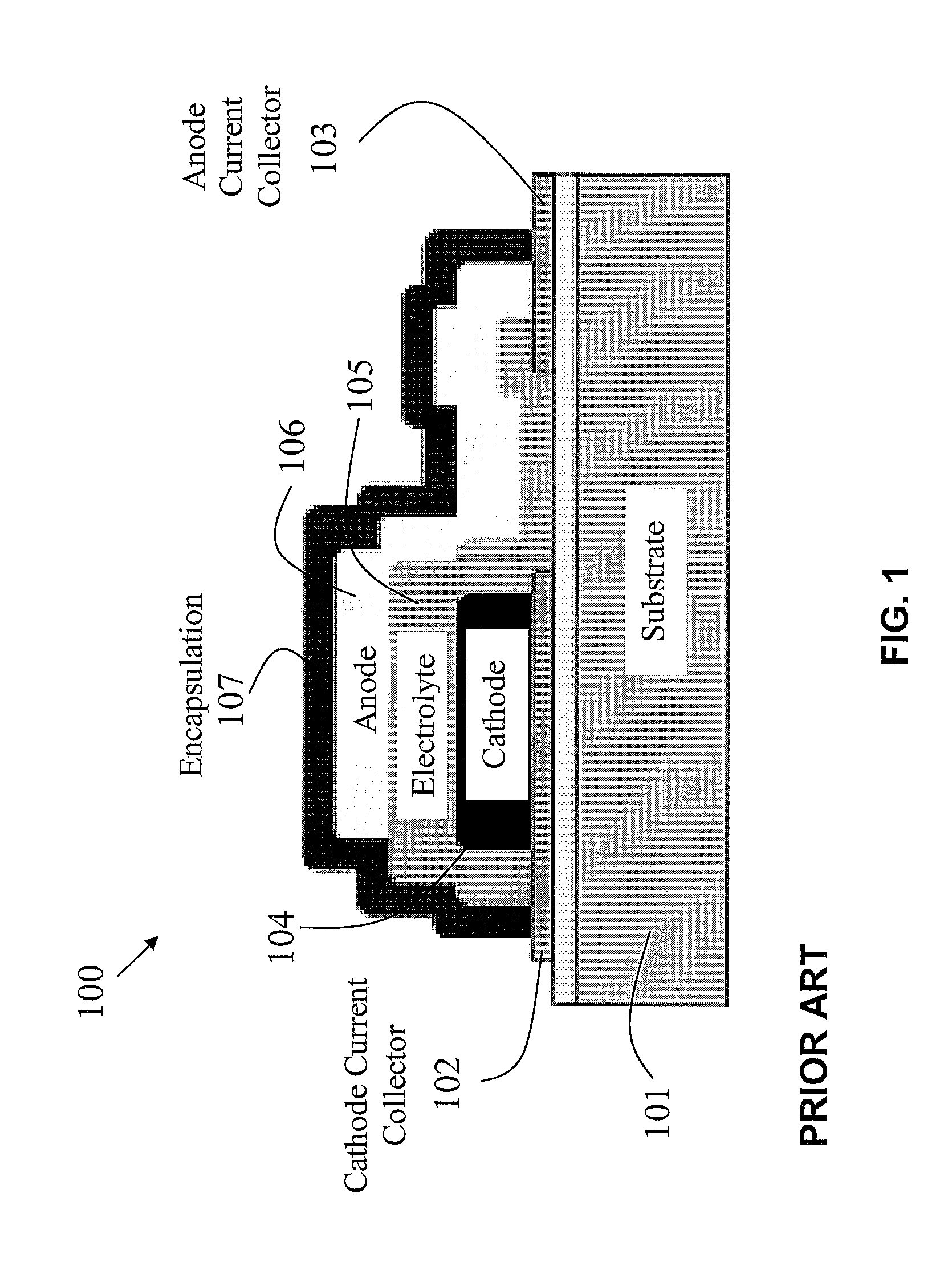
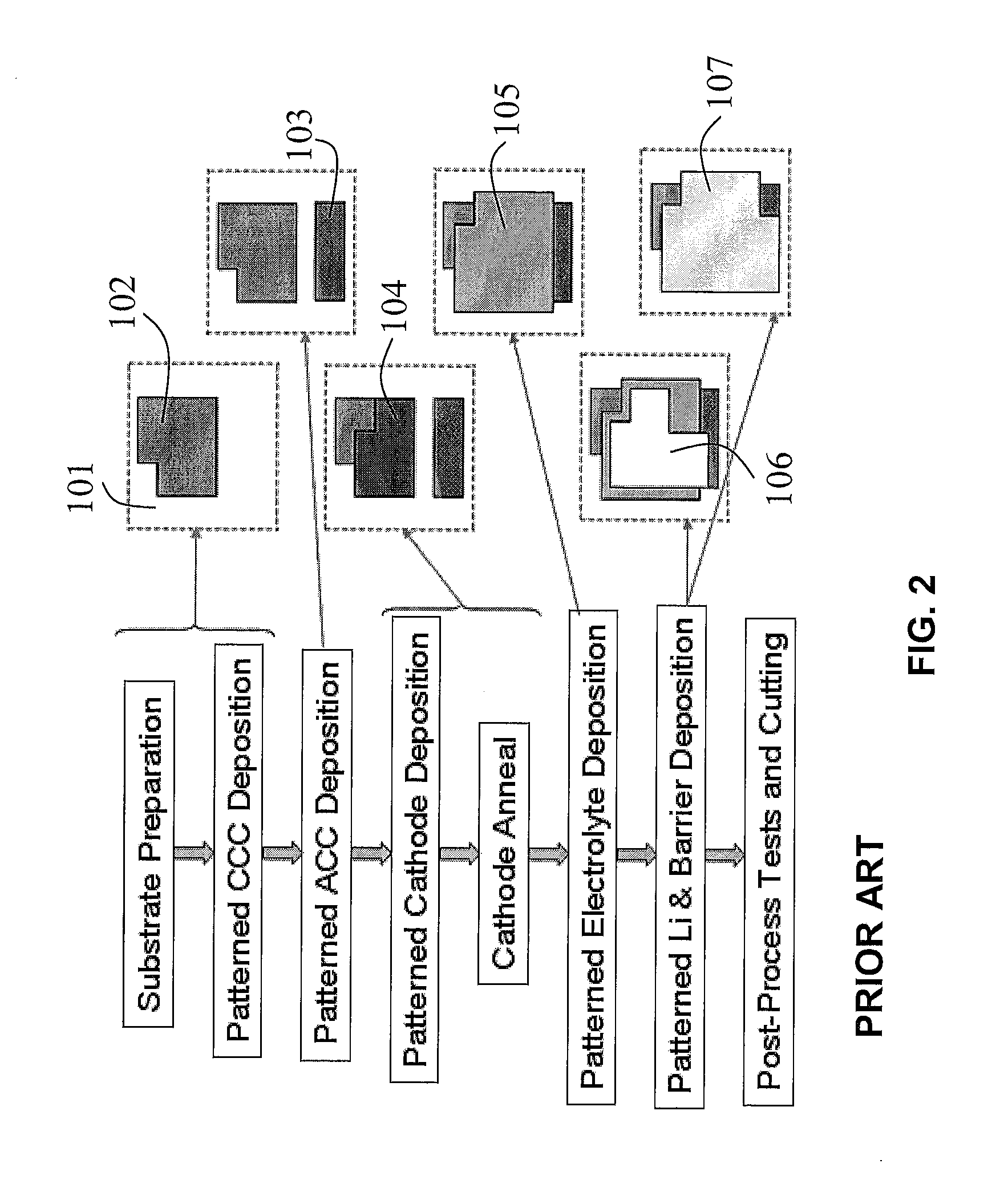
CROSS-REFERENCE TO RELATED APPLICATIONS[0001]This application claims the benefit of U.S. Provisional Application No. 61 / 739,635 filed Dec. 19, 2012.FIELD OF THE INVENTION[0002]Embodiments of the present invention relate generally to shadow mask-less fabrication processes for thin film batteries.BACKGROUND OF THE INVENTION[0003]Thin film batteries (TFBs) have been projected to dominate the micro-energy applications space. TFBs are known to exhibit several advantages over conventional battery technology such as superior form factors, cycle life, power capability and safety. FIG. 1 shows a cross-sectional representation of a typical thin film battery (TFB) and FIG. 2 shows a flow diagram for TFB fabrication along with corresponding plan views of the patterned TFB layers. FIG. 1 shows a typical horizontal TFB device structure 100 with anode current collector 103 and cathode current collector 102 are formed on a substrate 101, followed by cathode 104, electrolyte 105 and anode 106; altho...

Claims


Application Information

Patent Timeline
IPC IPC(8): H01M6/40C23C14/34H01M4/04C23C14/08
CPCH01M6/40H01M4/0426C23C14/34C23C14/088H01M10/0436H01M10/0585Y02E60/10Y02P70/50
Inventor SONG, DAOYINGJIANG, CHONGKWAK, BYUNG-SUNG LEO
Owner APPLIED MATERIALS INC
Learn More