Check patentability & draft patents in minutes with Patsnap Eureka AI!

Inspection method of flow sensor, inspection system and program recording medium with program for inspection system recorded thereon

Inactive Publication Date: 2015-11-19
HORIBA STEC CO LTD
View PDF1 Cites 5 Cited by
  • Summary
  • Abstract
  • Description
  • Claims
  • Application Information

AI Technical Summary

Benefits of technology

The present invention allows for faster inspection of flow sensors by reducing the fluid resistance and lowering the pressure required for starting the inspection. This is accomplished by opening multiple valves to decrease the fluid resistance in the flow paths, making the pressure needed for the inspection low even at small flow rates. As a result, the time required for inspection is significantly reduced.

Problems solved by technology

In a measurement flow rate value outputted from a flow sensor, there may possibly occur a time delay with respect to an actual flow rate value in some cases.
However, in the case where a measurement range of the inspection target flow sensor is set in a small flow rate range, the flow rate of the fluid capable of flowing into the flow path via the inspection target flow sensor is very small compared to a volume of the flow path.
Further, although the pressures in the flow paths capable of stably operating the inspection target flow sensors are different depending on the measurement ranges, the inspection is performed upon charging to substantially the same pressure regardless of the inspection target sensor in the current inspection system, and it cannot be said that the pressure is optimized in accordance with the inspection-target flow sensor.

Method used


Image

  • Inspection method of flow sensor, inspection system and program recording medium with program for inspection system recorded thereon
  • Inspection method of flow sensor, inspection system and program recording medium with program for inspection system recorded thereon
  • Inspection method of flow sensor, inspection system and program recording medium with program for inspection system recorded thereon

Examples


Embodiment Construction

[0033]The following describes an inspection system 100 of a flow sensor pertaining to one embodiment of the present invention with reference to the accompanying drawings.

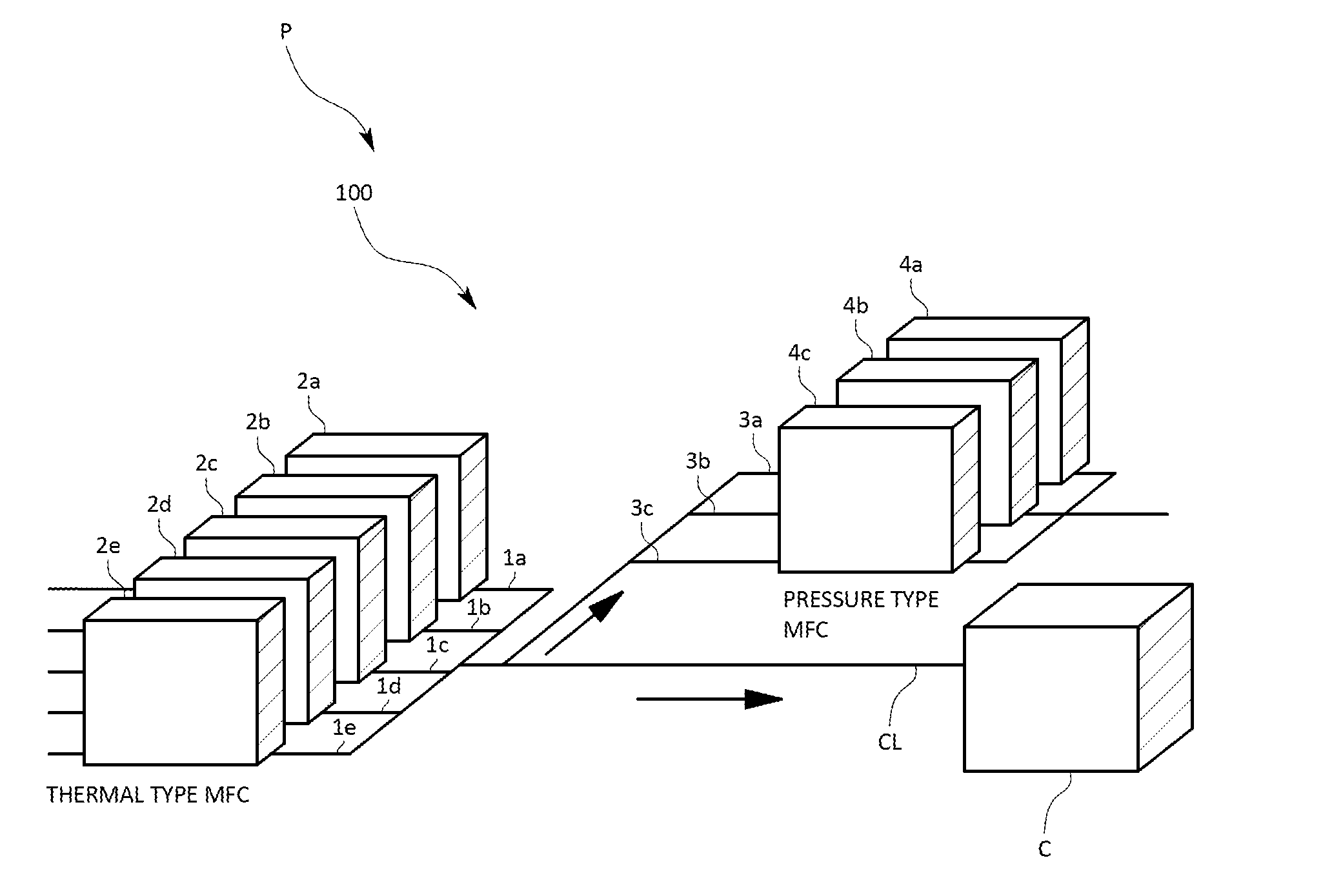
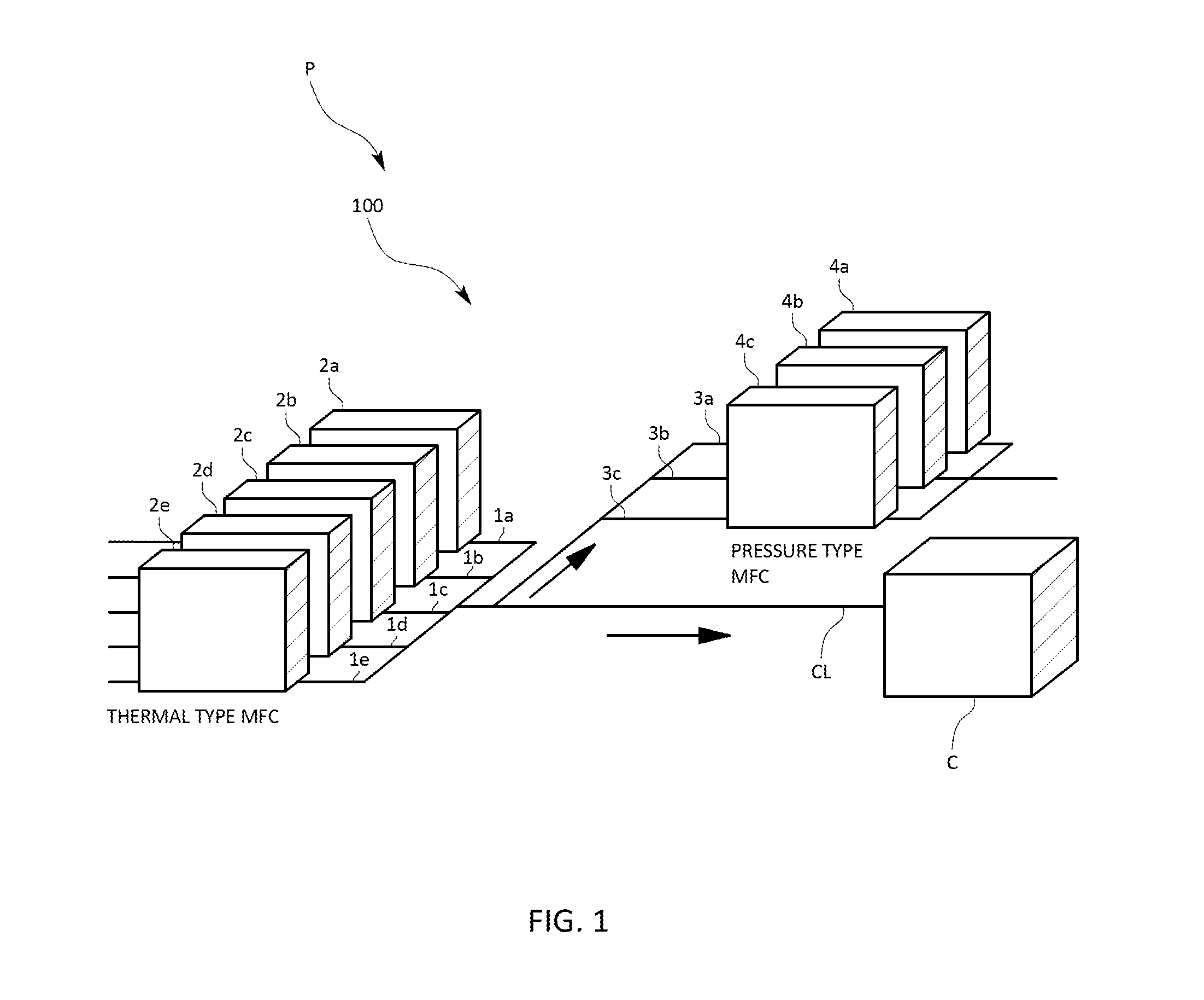
[0034]As shown in FIG. 1, an inspection system 100 for inspecting a flow sensor (referred to as “flow sensor inspection system” hereinafter) of the present embodiment, for example, serving as a part of a semiconductor manufacturing apparatus P is intended to be used for an inspection relating to a time delay of a flow sensor provided in a flow rate control device executing a flow rate control of various kinds of gas to be supplied to a process chamber C thereof.

[0035]In specific, this semiconductor manufacturing apparatus P is equipped with: gas supply lines 1a to 1e (collectively referred to as “gas supply line 1” hereinafter) in which various kinds of gas for semiconductor manufacturing such as, for example, process gas and etching gas flows; a chamber line CL and inspection lines 3a to 3c (collectively referred t...


PUM


Abstract

In order to provide an inspection system of a flow sensor capable of charging an appropriate pressure in a flow path in response to the inspection target flow sensor and significantly reducing a waiting time until a start of an inspection, the inspection system is provided with: fluid resistances respectively provided for a plurality of respective branch flow paths branched in a downstream of an upstream side flow path where the inspection target flow sensor is provided: valves respectively provided for the respective branch flow paths; a fluid sensor having at least a part thereof being provided in an upstream side than each of the fluid resistances for measuring a pressure or a flow rate of the fluid; and a valve opening / closing control part configured to allow a plurality of the valves to be in opened states at the time of inspecting the inspection target flow sensor.

Description

TECHNICAL FIELD[0001]The present invention relates to an inspection method of a flow sensor for inspecting at least a time delay contained in a flow rate value measured by the flow sensor, an inspection system and to a program recording medium with a program for the inspection system recorded thereon.BACKGROUND ART[0002]In a measurement flow rate value outputted from a flow sensor, there may possibly occur a time delay with respect to an actual flow rate value in some cases. In order to check whether or not such a time delay occurs or adjust the flow sensor to cancel such a time delay, an inspection work of the flow sensor has been performed (see Patent Literature 1).[0003]The inspection as to a time delay of a flow sensor is specifically performed as follows. First, a flow sensor to be calibrated (referred to as “inspection target flow sensor” hereinafter), a slow sensor as a reference (referred to as “reference flow sensor” hereinafter) and a fluid resistance for generating a pred...

Claims


Application Information

Patent Timeline
IPC IPC(8): G05D16/20
CPCG05D16/2006Y10T137/7758Y10T137/0396G05D7/0641
Inventor YASUDA, TADAHIROSHIRAI, TAKASHI
Owner HORIBA STEC CO LTD
Features
  • R&D
  • Intellectual Property
  • Life Sciences
  • Materials
  • Tech Scout
  • Unparalleled Data Quality
  • Higher Quality Content
  • 60% Fewer Hallucinations
Learn More