Environmental Defense Shield

a technology of environmental protection and shield, which is applied in the direction of machines/engines, efficient propulsion technologies, combustion air/fuel air treatment, etc., can solve the problems of constant possibility of debris ingestion, significant damage, and structural problems of compressor blades, so as to reduce the disruption of vortices, reduce the distortion of air intake opening flow, and eliminate additional stress on other structural members.

Active Publication Date: 2015-12-03
SHIELD AERODYNAMICS
View PDF7 Cites 10 Cited by
  • Summary
  • Abstract
  • Description
  • Claims
  • Application Information

AI Technical Summary

Benefits of technology

[0009]The present invention is directed to an environmental defense shield for a turbine engine, which serves to block debris and other foreign objects from entering the engine with minimal interference to the airflow into the engine. The present invention is designed to deflect solid mass energy, rather than to absorb it, eliminating additional stress on other structural members of the cowling and attachments, wing, or body members of the aircraft. This is accomplished by means of shape, construction and/or material composition. In one aspect, the present invention is directed to an environmental defense shield for a turbine engine on an aircraft, the environmental defense shield comprising a plurality of aerodynamic vanes, wherein each of the aerodynamic vanes comprises a leading edge and a trailing edge wherein the leading edge and trailing edge are not equidistant at all points along the length of each of the plurality of aerodynamic vanes, and further wherein each of the plurality of aerodynamic vanes comprises a symmetrical airfoil cross-sectional shape. The shield mitigates distortion of the air intake opening flow caused by boundary layer differences, crosswinds and/or swirling, such as reducing the disruption of vortices around the air intake ...

Problems solved by technology

The changing flow conditions can cause flow separation in the compressor, a compressor stall, and can cause structural problems for the compressor blades.
Due to the design and function of a turbine engine's air inlet, the possibility of ingestion of debris always exists.
This causes significant damage, particularly to the compressor.
However, FOD damage caused by bird strikes or ice ingestion can also occur, and may result in total destruction of an engine.
In addition, a vortex pattern of turbulent air is caused, partially by air flow over the lipskin in several...

Method used


Image

  • Environmental Defense Shield
  • Environmental Defense Shield
  • Environmental Defense Shield

Examples


Embodiment Construction

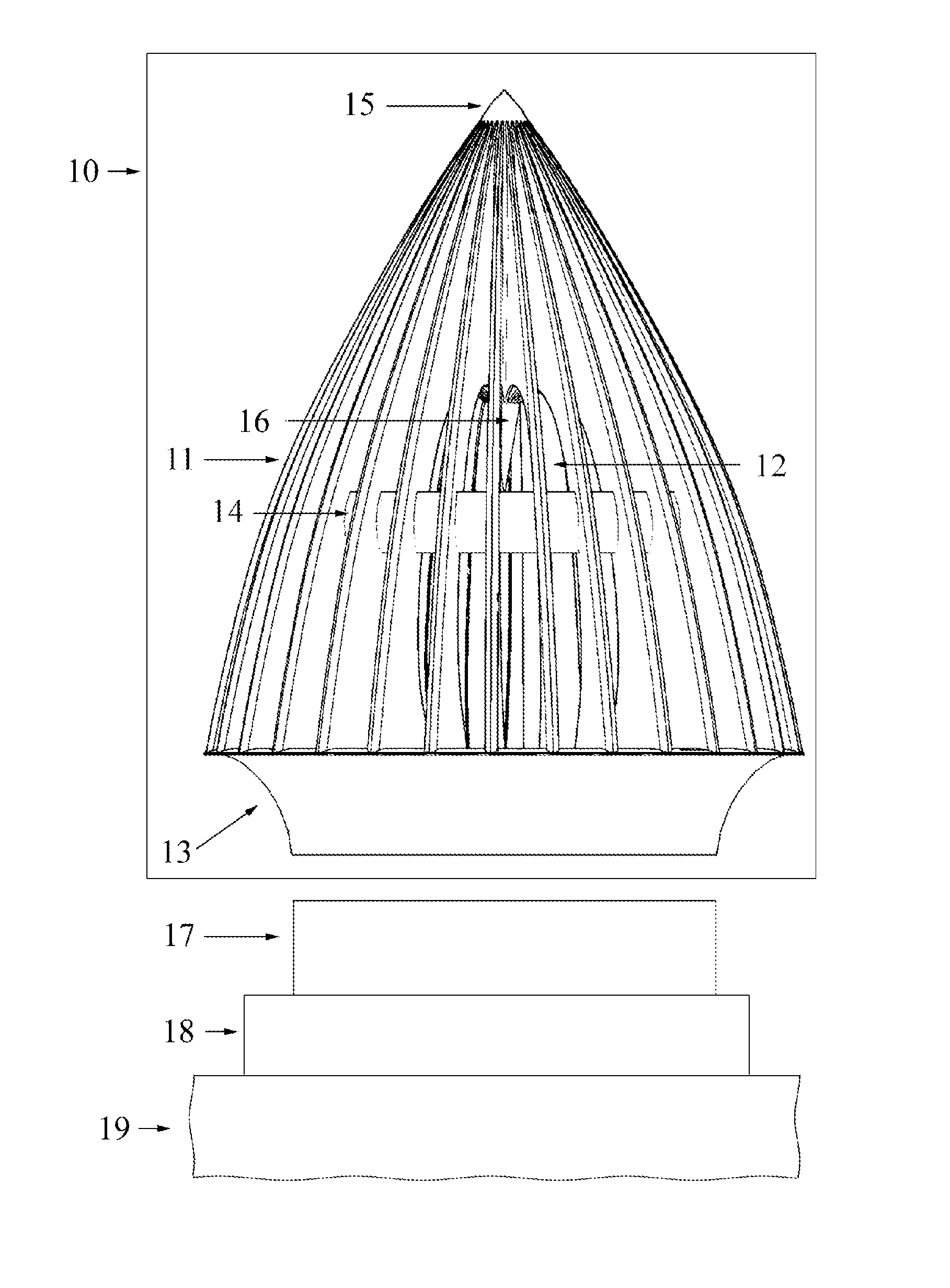
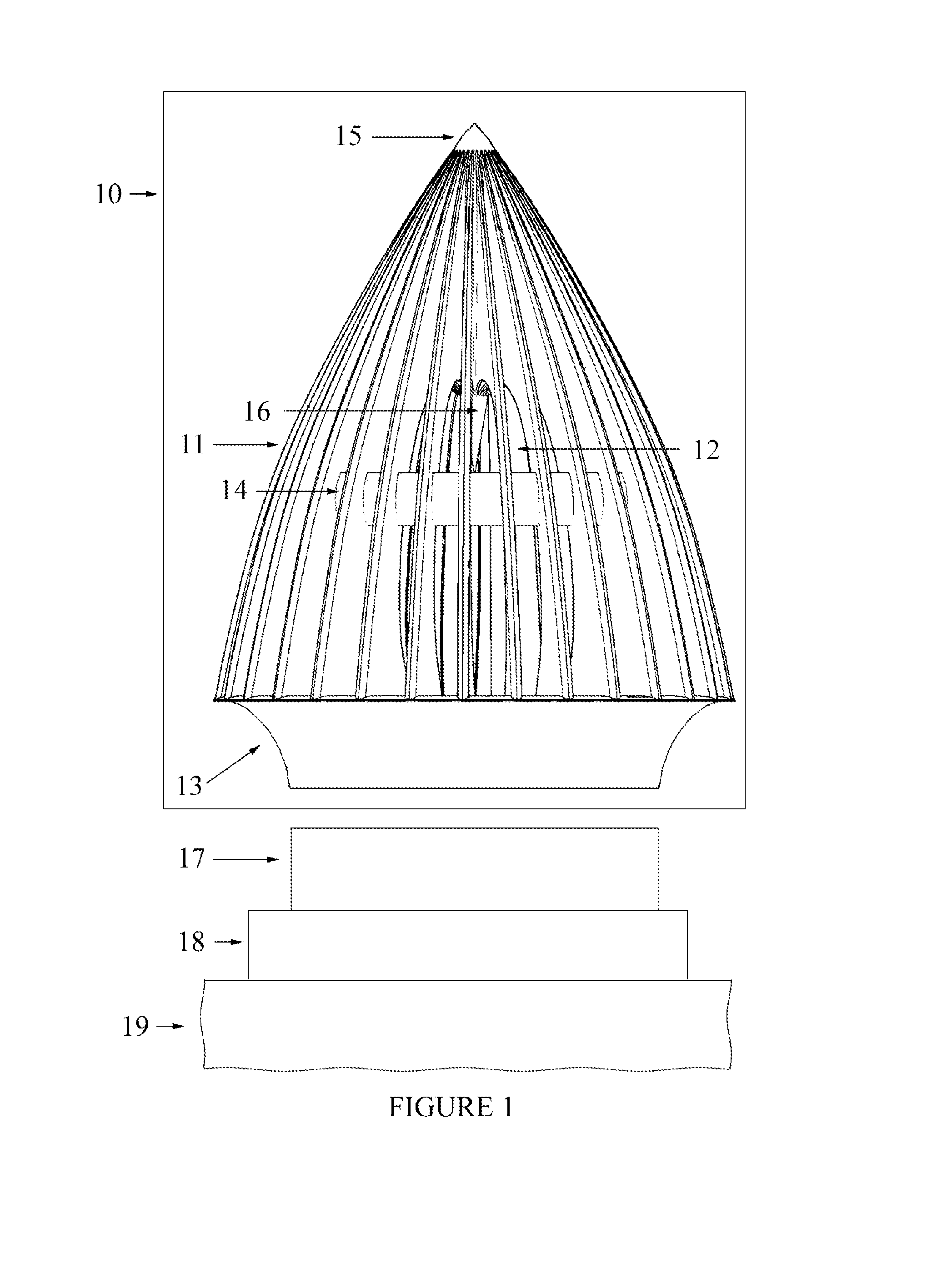
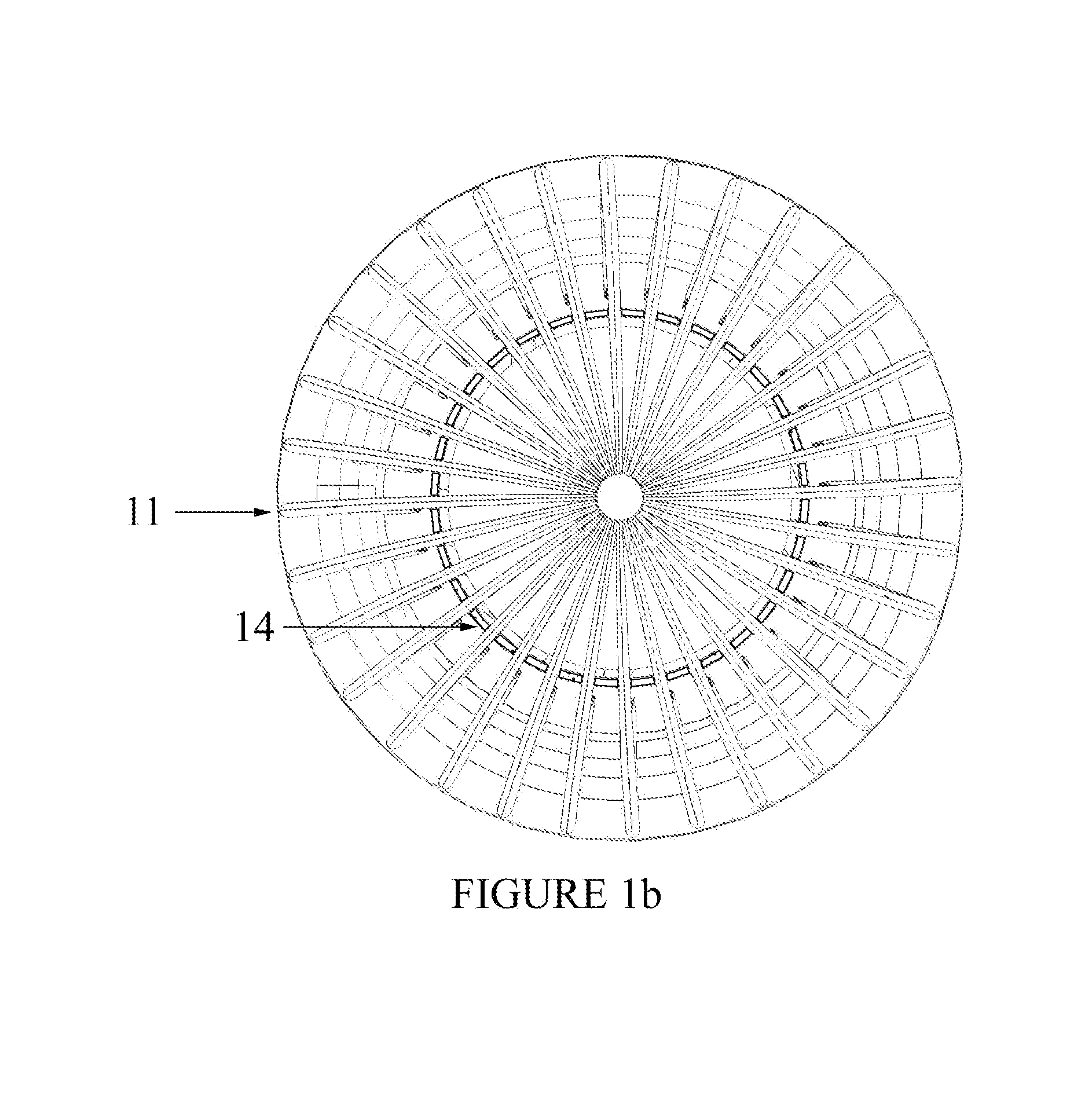
[0023]Referring now to the drawings wherein is depicted for purposes of illustrating preferred embodiments of the present invention only, and not for purposes of limiting the same, FIGS. 1-9 illustrate a defense shield which is constructed in accordance with the present invention.

[0024]Referring now to FIGS. 1, 1b, and 1c, one preferred embodiment of the present invention is described for the defense shield 10, which includes vanes 11, the plenum space 12, the base in a partial ring torus or “C” shape 13, the band stiffener 14, the nose 15, the reverse cone 16, the air intake opening 17, the engine 18 and the aircraft 19. The vanes 11 emanate from the tangent point of the side of the base 13, where it connects to or merges with the base 13, to reduce the trapping of any flow of air that can cause drag or turbulence. The vanes 11 will project forward in a symmetrical airfoil shape. The band stiffener 14 is a ring having an airfoil shape that is set into the vanes 11 which projects fo...


PUM


Abstract

An environmental defense shield includes symmetric airfoil-shaped vanes contributing to and positioned around a plenum space and positioned in front of a turbine engine. An annular band stiffener is set into the vanes, which projects forward in a diminishing size, the vanes merging together to create or attaching to a solid nose. The environmental defense shield serves to protect the engine from debris while also smoothing airflow into the engine.

Description

CROSS-REFERENCE TO RELATED APPLICATIONS[0001]This application is a continuation of international patent application no. PCT / US2013 / 062392, filed on Sep. 27, 2013, and entitled “Environmental Defense Shield,” which in turn claims the benefit of provisional patent application No. 61 / 706,400, filed on Sep. 27, 2012, and entitled “Environmental Defense System.” Such applications are incorporated herein by reference in their entirety.BACKGROUND[0002]The present invention relates generally to turbine engines and more specifically to protective devices for turbine engines that prevent debris from entering the engine, and to smooth turbulent air flow.[0003]Turbine engines produce thrust by increasing the velocity of the air flowing through the engine. A turbine engine consists primarily of an air inlet, compressor, combustion chamber or chambers, turbine section, and exhaust. There are several different types of turbine engines, but all turbine engines have some parts in common. All turbine...

Claims


Application Information

Patent Timeline
IPC IPC(8): F02C7/047F02C7/055
CPCF02C7/05B64D33/02B64D2033/022F02C7/055Y02T50/60
Inventor SNYDER, DENNIS
Owner SHIELD AERODYNAMICS
Why Eureka
Try Eureka