Drive circuitry and method for a vibration gyroscope
- Summary
- Abstract
- Description
- Claims
- Application Information
AI Technical Summary
Benefits of technology
Problems solved by technology
Method used
Image

Examples
Embodiment Construction
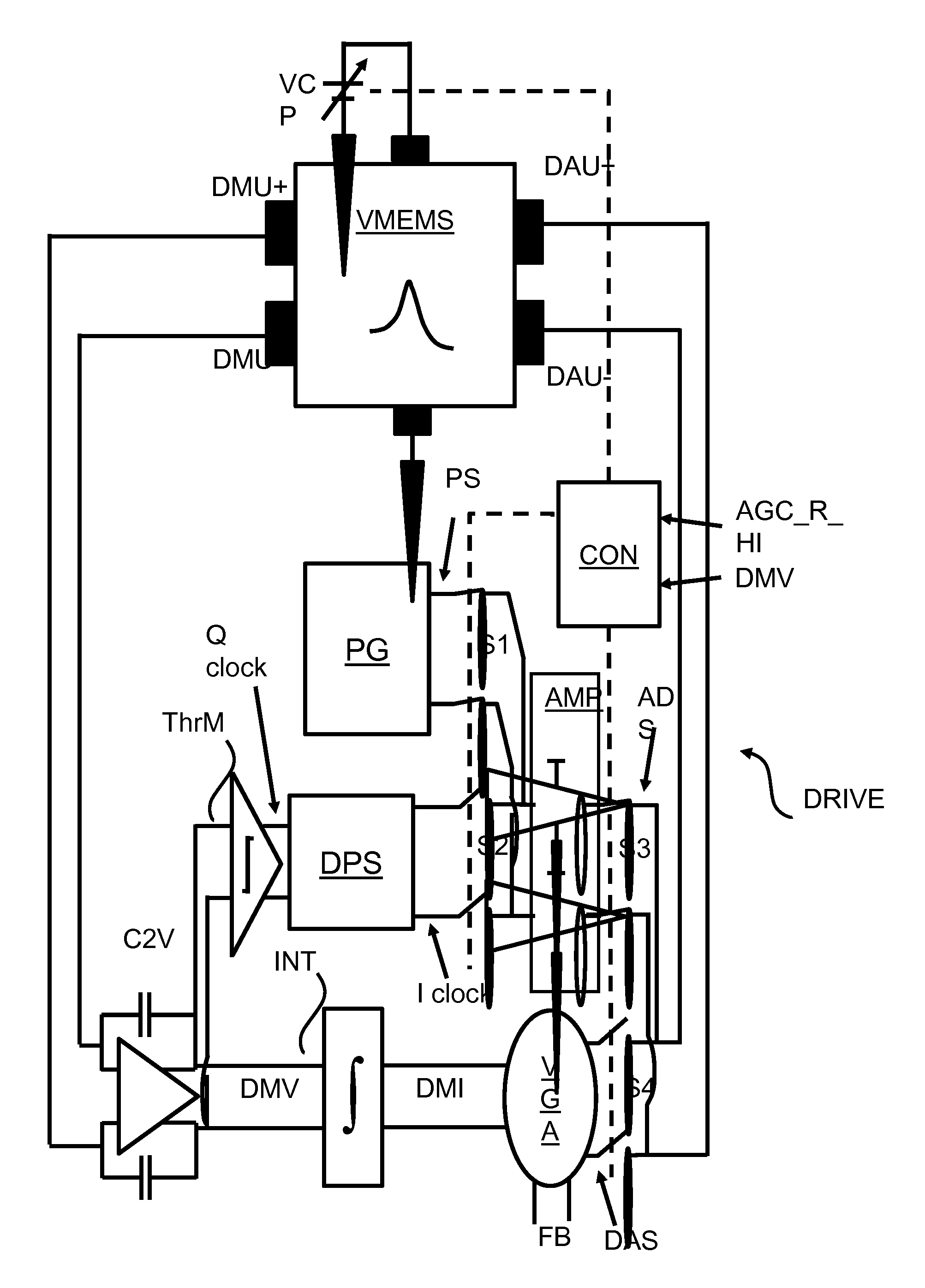
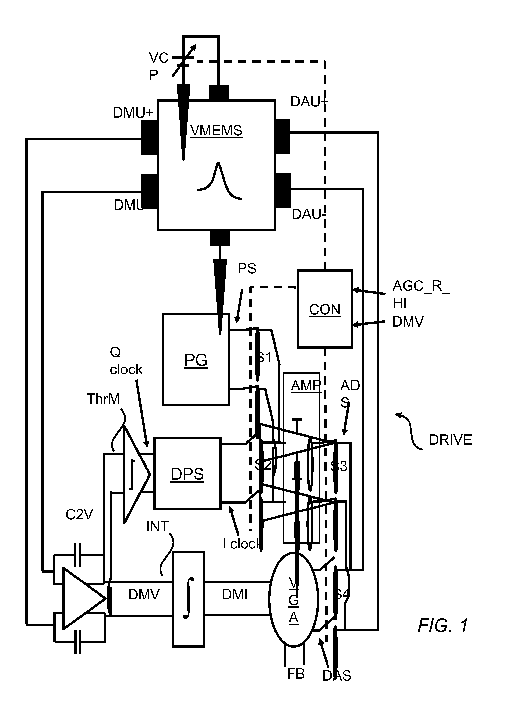
[0014]FIG. 1 schematically shows a block diagram of an example of an embodiment of a drive circuitry DRIVE coupled to a vibration MEMS VMEMS. The drive circuitry DRIVE is arranged to drive the vibration MEMS VMEMS by way of applying suitable signals to drive actuation units DAU+ and DAU−.
[0015]The drive circuitry DRIVE comprises a voltage supply unit VCP, a capacitance-to-voltage converter C2V, a threshold detector ThrM, a digital phase shifter DPS, an integrator IN, a variable gain amplifier VGA, a pulse signal generator PG and a controller CON.
[0016]The voltage supply unit VCP may be arranged to deliver a supply voltage to a primary resonator of the vibration gyroscope. The voltage supply unit VCP may comprise a charge pump VCP arranged to create a charge pump voltage out of power source voltage. An example of a charge pump is a pump transferring a power source voltage of 1.75 V into a charge pump voltage of 10.5 V. Instead of a charge pump other types of voltage supply units may ...
PUM
 Abstract
Description
Claims
Application Information
 - R&D Engineer
- R&D Manager
- IP Professional
- Industry Leading Data Capabilities
- Powerful AI technology
- Patent DNA Extraction
Browse by: Latest US Patents, China's latest patents, Technical Efficacy Thesaurus, Application Domain, Technology Topic.
© 2024 PatSnap. All rights reserved.Legal|Privacy policy|Modern Slavery Act Transparency Statement|Sitemap