
Pulse detection apparatus and pulse detection method

a detection apparatus and pulse technology, applied in the field of pulse detection apparatus and pulse detection method, can solve the problems of limited movement of the subject's body, considerable limited environment for performing measurement, and inability to move the subject's body in some degree, so as to reduce the risk of noise and less susceptible to movement of the subject.

Inactive Publication Date: 2015-12-03
NAT UNIV CORP KYUSHU INST OF TECH (JP)
View PDF10 Cites 5 Cited by
  • Summary
  • Abstract
  • Description
  • Claims
  • Application Information

AI Technical Summary

Benefits of technology

The present invention is about a device and method for detecting pulses. The new technology is less affected by the subject's movement and can better distinguish pulses caused by the body's movement from real pulses.

Problems solved by technology

However, in both the optical method and the piezoelectric method, since it is required to mount the sensor to the body of a subject, the movement of the body of subject will be limited to some extent.
Particularly, in the piezoelectric method, in order to perform precise measurement, it is required to employ a pressing means to correctly press the piezoelectric sensor on directly above the artery, and therefore not only the movement of the body of the subject, but also the environment for performing measurement will be considerably limited.

Method used


Image

  • Pulse detection apparatus and pulse detection method
  • Pulse detection apparatus and pulse detection method
  • Pulse detection apparatus and pulse detection method

Examples


modification 1

(Modification 1)

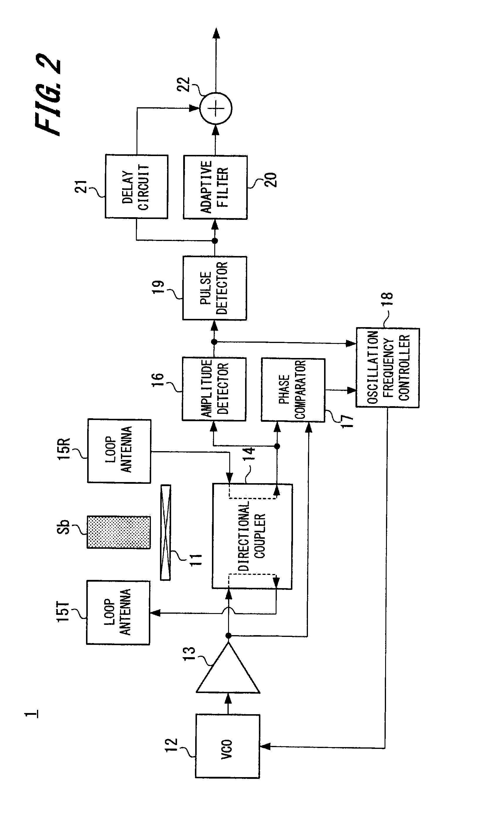
[0053]The aforesaid embodiment is described using an example in which the pulse signal is detected based on the amplitude detected by the amplitude detector 16; however, the present invention is not limited thereto. It is also possible to measure transfer characteristics of the loop antenna 15T and the loop antenna 15R, and detect characteristic change of the obtained transfer characteristics to thereby detect the pulse signal. For example, an S parameter can be used as the transfer characteristics. The S parameter is a parameter that indicates changes in amplitudes and phases of an incident signal and a reflected signal, and can be calculated based on the values of electric powers inputted to / outputted from the directional coupler 14 (see FIG. 2).

[0054]FIG. 6 is a block diagram showing a configuration in which an input reflection coefficient (S11), which is an example of the S parameter, is calculated, and the change of the calculated S11 in the time direction is de...

modification 2

(Modification 2)

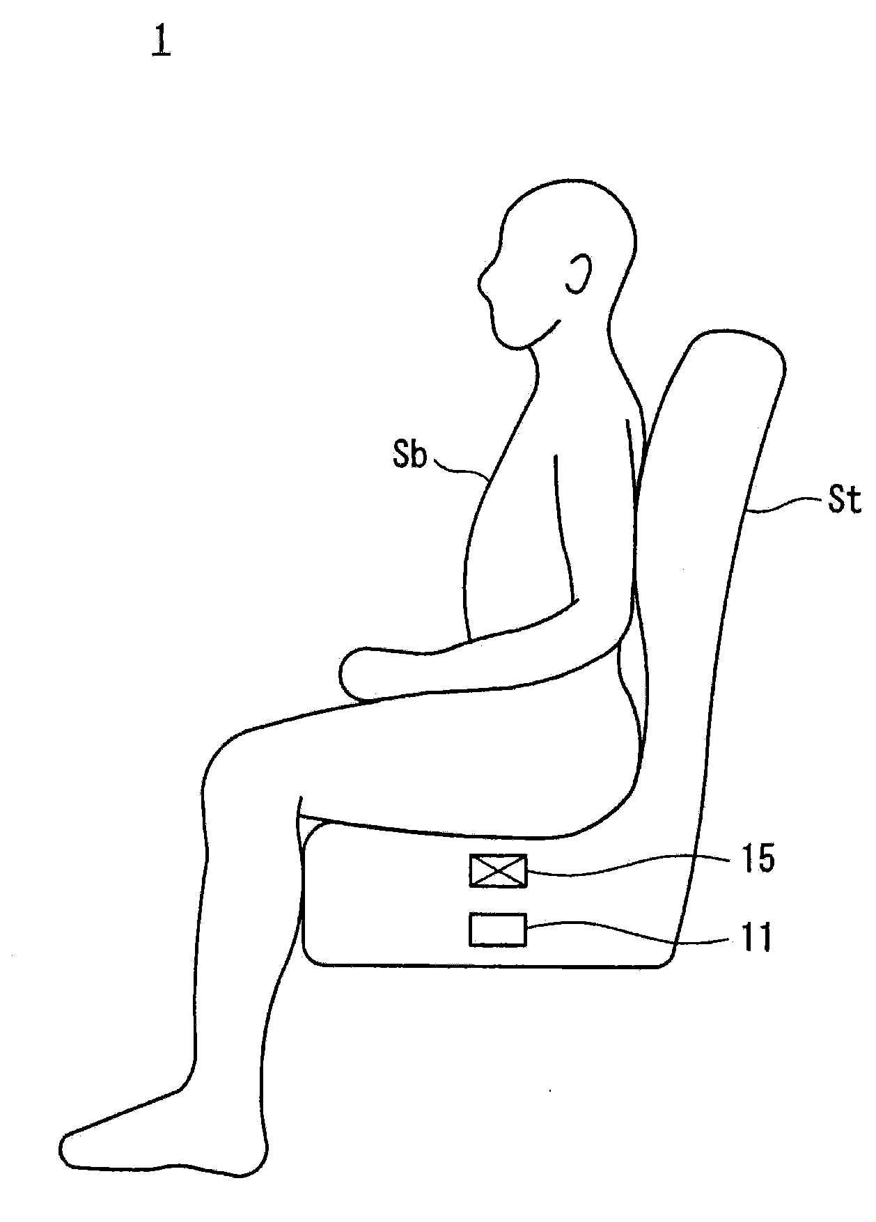
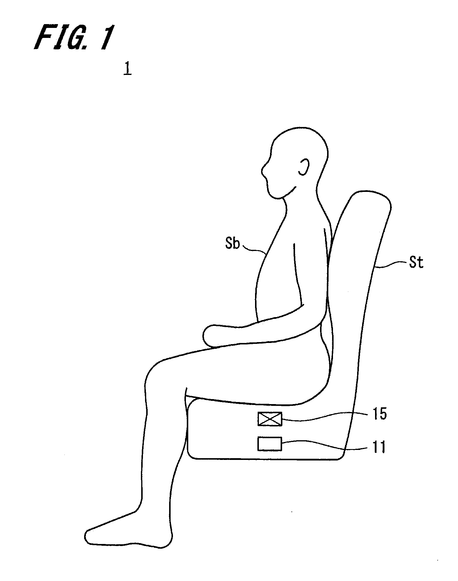
[0062]The above-described present embodiment is described using an example in which the pulse detection apparatus 1 (or the pulse detection apparatus 1A) is mounted in the vehicle; however, the present invention is not limited thereto. The pulse detection apparatus of the present invention may be applied to any form as long as the form allows detection of data sufficient for detection of the pulse. The form allowing detection of data sufficient for detection of the pulse is achieved by, for example, arranging the sensor portion, which is configured by the magnet 11, the loop antenna 15T, and the loop antenna 15R, at a position close to the body of the subject Sb.

[0063]FIG. 9 shows an example in which the sensor portion of the pulse detection apparatus 1 is configured as an earphone-type sensor. Incidentally, FIG. 9 shows only the sensor portion of the pulse detection apparatus 1. In FIG. 9, the sensor portion is shown as an “earphone-type sensor 10.” The earphone-typ...


PUM


Abstract

Provided is a pulse detection apparatus and a pulse detection method less susceptible to movement of a subject and less susceptible to noise. An oscillation frequency controller is configured to cause a frequency variable oscillator to oscillate at a predetermined oscillation frequency, which is a frequency within a range assumed as a resonance frequency of a molecule of a predetermined constituent constituting the blood flowing through a human body. The oscillation frequency controller also controls an oscillation frequency based on a phase difference signal and an amplitude signal, wherein the phase difference signal indicates the phase difference between a transmission signal transmitted from an antenna to the human body and a reception signal received by the antenna, and the amplitude signal indicates the magnitude of the amplitude of the received signal. A pulse detector detects the change of the amplitude signal in an amplitude direction as a pulse signal.

Description

TECHNICAL FIELD[0001]The present invention relates to a pulse detection apparatus and a pulse detection method preferably applicable to, for example, a medical device, an in-vehicle biosensor and the like.BACKGROUND ART[0002]Conventionally, a method for detecting a change in volume of a blood vessel resulting from fluctuations and a method for detecting a change in pressure in the blood vessel are known as methods for measuring a pulse. The change in the volume of the blood vessel resulting from fluctuations is typically detected by using an optical method, while the change in the pressure in the blood vessel is typically detected by using a piezoelectric method. In the optical method, a living body is irradiated with a light in a wavelength range of the hemoglobin contained in the blood, and the strength of the transmitted light or reflected light is converted into an electrical signal to thereby detect the pulse. In the piezoelectric method, a piezoelectric sensor is pressed again...

Claims


Application Information

Patent Timeline
Patent Type & Authority Applications(United States)
IPC IPC(8): G01R33/563G01R33/34G01R33/60
CPCG01R33/5635G01R33/34092G01R33/60A61B5/6891A61B5/6893A61B5/024A61B5/055A61B5/18G01R33/341G01R33/3607
Inventor SATO, YASUSHI
Owner NAT UNIV CORP KYUSHU INST OF TECH (JP)
Learn More