Compensation of Dose Inhomogeneity Using Overlapping Exposure Spots

a multi-beam exposure and dose inhomogeneity technology, applied in the direction of electrical discharge tubes, instruments, computing, etc., can solve the problems of unavoidable influence of the dose rate of each beamlet, inability to cover time-dependent or varying effects, etc., to achieve the effect of reducing the error per dose increment, improving the compensation method, and increasing the degree of overlap

a multi-beam exposure and dose inhomogeneity technology, applied in the direction of electrical discharge tubes, instruments, computing, etc., can solve the problems of unavoidable influence of the dose rate of each beamlet, inability to cover time-dependent or varying effects, etc., to achieve the effect of reducing the error per dose increment, improving the compensation method, and increasing the degree of overlap

US20150347660A1Active Publication Date: 2015-12-03IMS NANOFABTION

Image

  • Compensation of Dose Inhomogeneity Using Overlapping Exposure Spots
  • Compensation of Dose Inhomogeneity Using Overlapping Exposure Spots
  • Compensation of Dose Inhomogeneity Using Overlapping Exposure Spots

Examples


Embodiment Construction

[0053]It should be appreciated that embodiments of the invention are not restricted to the embodiments discussed in the following, which merely represent suitable implementations of the invention.

Lithographic Apparatus

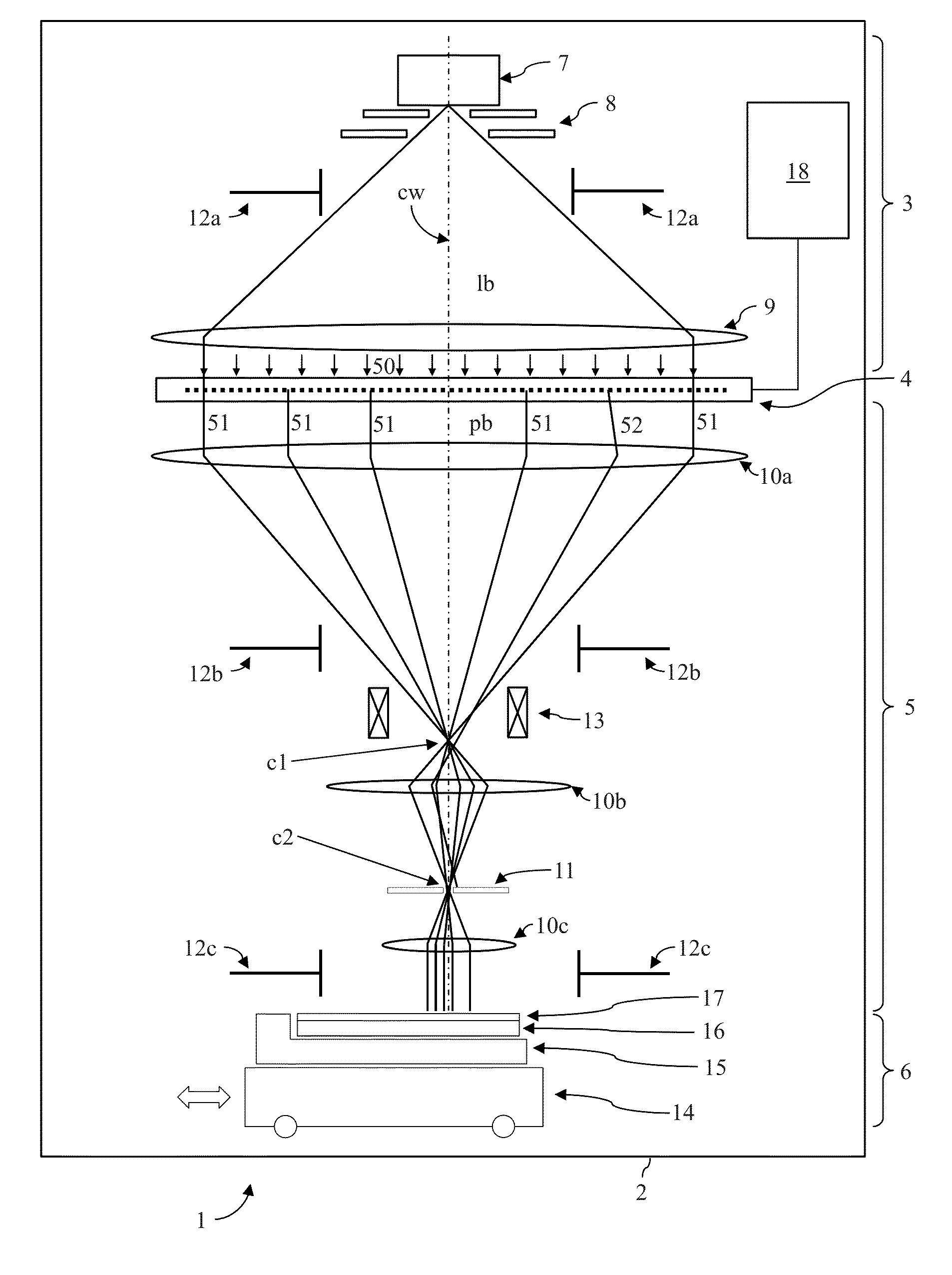
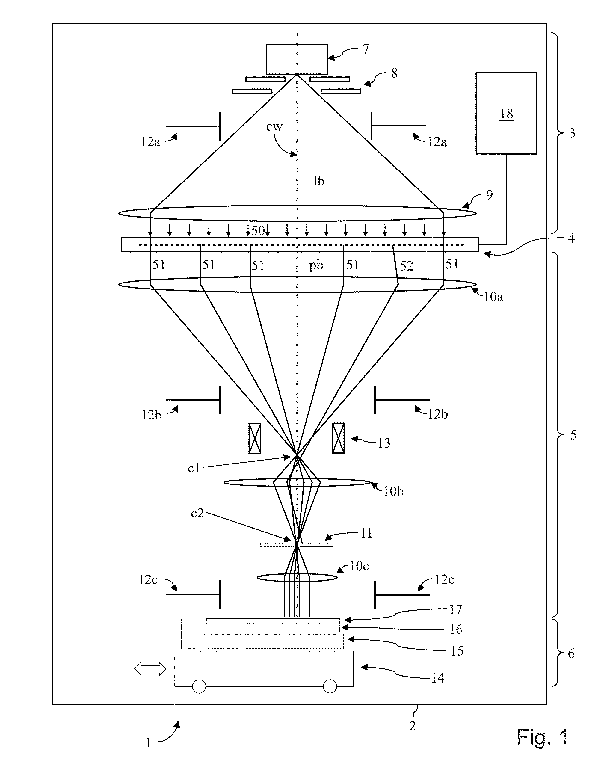
[0054]An overview of a lithographic apparatus as known from prior art employing the preferred embodiment of the invention is shown in FIG. 1. In the following, only those details are given as needed to disclose certain embodiments of the invention such that one of ordinary skill in the art can practice the various embodiments of the invention; for the sake of clarity, the components are not shown to size in FIG. 1. The main components of the lithography apparatus 1 are—corresponding to the direction of the lithography beam lb, pb which in this example runs vertically downward in FIG. 1—an illumination system 3, a pattern definition (PD) system 4, a projecting system 5, and a target station 6 with the substrate 16. The whole apparatus 1 is contained in a vacuum housing ...


PUM


Abstract

An exposure pattern is computed which is used for exposing a desired pattern on a target by means of a particle beam and a blanking aperture array in a particle-optical lithography apparatus, taking into account a non-uniform current dose distribution as generated by the beam over the positions of the apertures of the blanking aperture array: From the desired pattern a nominal exposure pattern is calculated as a raster graphics comprising nominal dose values for the pixels of the raster graphics; based on a map of the current dose distribution, which correlates each aperture with a current factor describing the current dose of the beam at the location of the aperture, a compensated dose value is calculated for each pixel, by dividing its nominal dose value by the compensation factor corresponding to the current factor of the corresponding aperture(s); and for each pixel, a discrete value is determined by selecting a value from a discrete gray scale so as to approximate the compensated dose value.

Description

CROSS-REFERENCE TO RELATED APPLICATION[0001]The present application claims priority to European Application No. 14170611.9, filed May 30, 2014. The disclosure of European Application No. 14170611.9 is incorporated by reference herein its entirety.FIELD OF THE INVENTION AND DESCRIPTION OF PRIOR ART[0002]Embodiments of the invention relate to a charged-particle multi-beam exposure apparatus for forming a pattern on a surface of a substrate or target by means of a beam of energetic electrically charged particles. More in detail, in many embodiments, the invention relates to a method for computing an exposure pattern for exposing a desired pattern on a target in a charged-particle multi-beam lithography apparatus, in which a particle beam is directed to and illuminates a pattern definition device comprising an aperture array composed of a plurality of blanking apertures through which said particle beam penetrates for writing said desired pattern by exposing a multitude of pixels within ...

Claims


Application Information

Patent Timeline
03 Dec 2015
Publication
US20150347660A1
IPC
G06F17/50
CPC
G06F17/5081; G06F17/5072; H01J37/304; H01J37/3177; H01J2237/24535; H01J2237/31761; G06F30/392; G06F30/398
Inventors
PLATZGUMMER, ELMAR; REITER, RAFAEL