Reduced Size Optical Coupler for Fluorescence Detection

a fluorescence detection and optical coupler technology, applied in the direction of fluorescence/phosphorescence, instruments, catheters, etc., can solve the problems of inefficiency, light detection, and inability to analyze the band wavelength in a certain way, so as to reduce the size of the cgm device and potential manufacturing costs, reduce light transmission inefficiencies, and increase the initial light emission

Active Publication Date: 2015-12-10
EMBECTA CORP
View PDF9 Cites 3 Cited by
  • Summary
  • Abstract
  • Description
  • Claims
  • Application Information

AI Technical Summary

Benefits of technology

[0010]Another aspect of embodiments of the present invention is to provide an optical coupler configured to reduce the size of the CGM device and potential manufacturing costs.
[0011]Another aspect of embodiments of the present invention is to reduce light transmission inefficiencies which contribute to the need for greater initial light emission, thereby saving power and battery life.
[0012]Another aspect of embodiments of the present invention is to reduce the failure rate of the mass produced CGM devices by limiting the number of distinct components that need to be aligned with one another during assembly.
[0014]The foregoing and / or other aspects of the present invention are achieved by providing a CGM device wherein an optical coupler is formed by a reduced number of distinct components and transmits light from a light source to a GBP and from the GBP to a photodiode while significantly reducing the amount of stray light, thereby improving the efficiency and accuracy of the CGM device.

Problems solved by technology

As a result, less light is detected overall, because the light in the signal band that illuminates the reference band photodiode will not be detected, and the light in the reference band that illuminates the signal band photodiode likewise will not be detected.
This inefficiency can dilute the analysis of the band wavelengths and can require greater initial light emission from a light source, requiring more energy and battery life.
This use of three distinct glass filters can add manufacturing and assembly costs and can increase the possibility of failure due to improper alignment of the glass filters.
The use of three glass filter can also increase the overall size of the CGM device making it more inconvenient and uncomfortable for a user.
This filter configuration can lead to higher levels of stray light that is lost during transmission, thereby increasing light efficiency and decreasing the accuracy of the photodiode detecting the signal and reference bands.
With the CGM device designs above, there are concerns over light transmission inefficiencies, which contribute to the need for greater initial light emission, requiring greater power input / battery life.
Additional concerns include manufacturing costs associated with the assembly of multiple components and the significant overall size of the CGM device.

Method used


Image

  • Reduced Size Optical Coupler for Fluorescence Detection
  • Reduced Size Optical Coupler for Fluorescence Detection
  • Reduced Size Optical Coupler for Fluorescence Detection

Examples


Embodiment Construction

[0032]As will be appreciated by one skilled in the art, there are numerous ways of carrying out the examples, improvements and arrangements of CGM devices disclosed herein. Although reference will be made to the illustrative embodiments depicted in the drawings and the following descriptions, the embodiments disclosed herein are not meant to be exhaustive of the various alternative designs and embodiments that are encompassed by the disclosed invention.

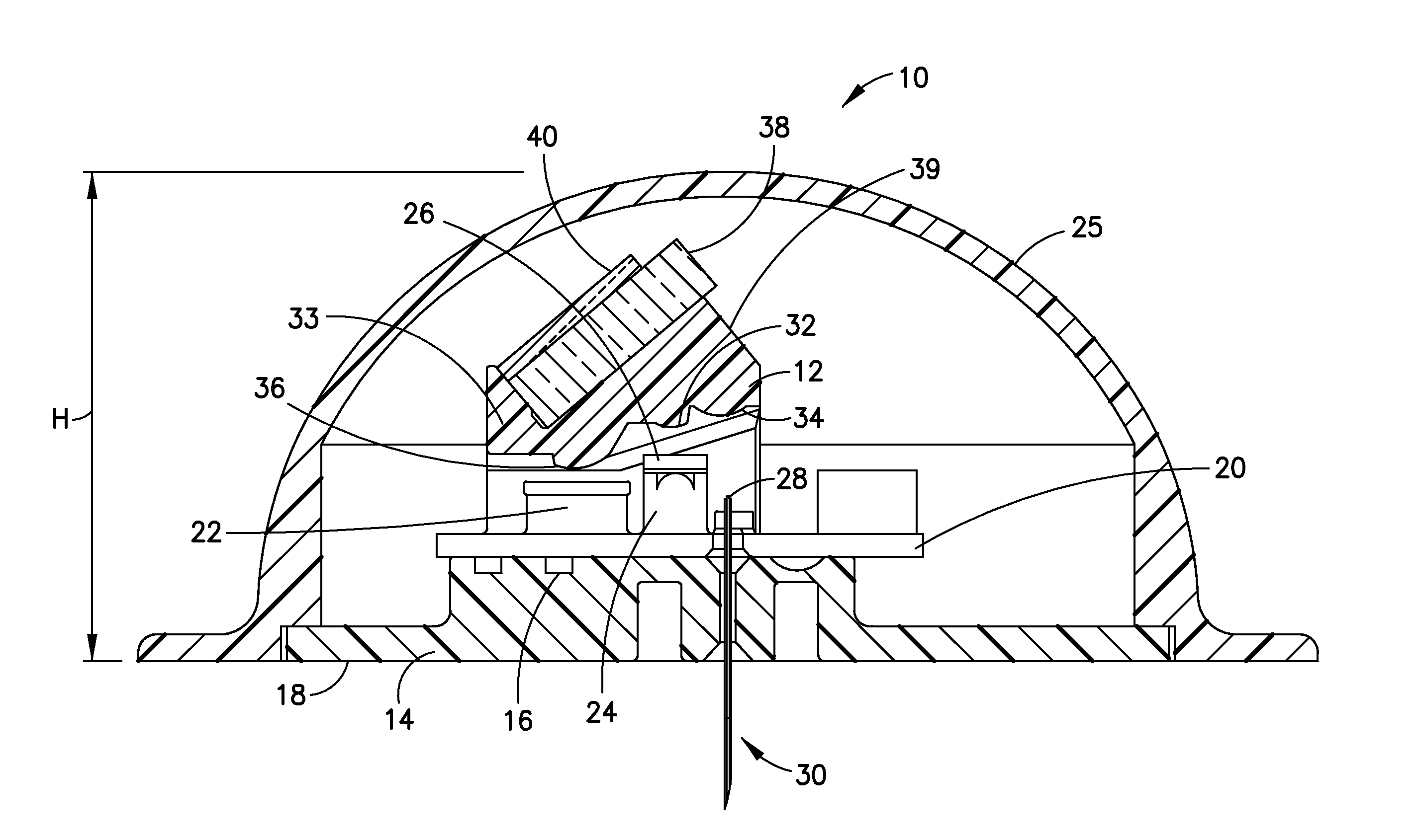
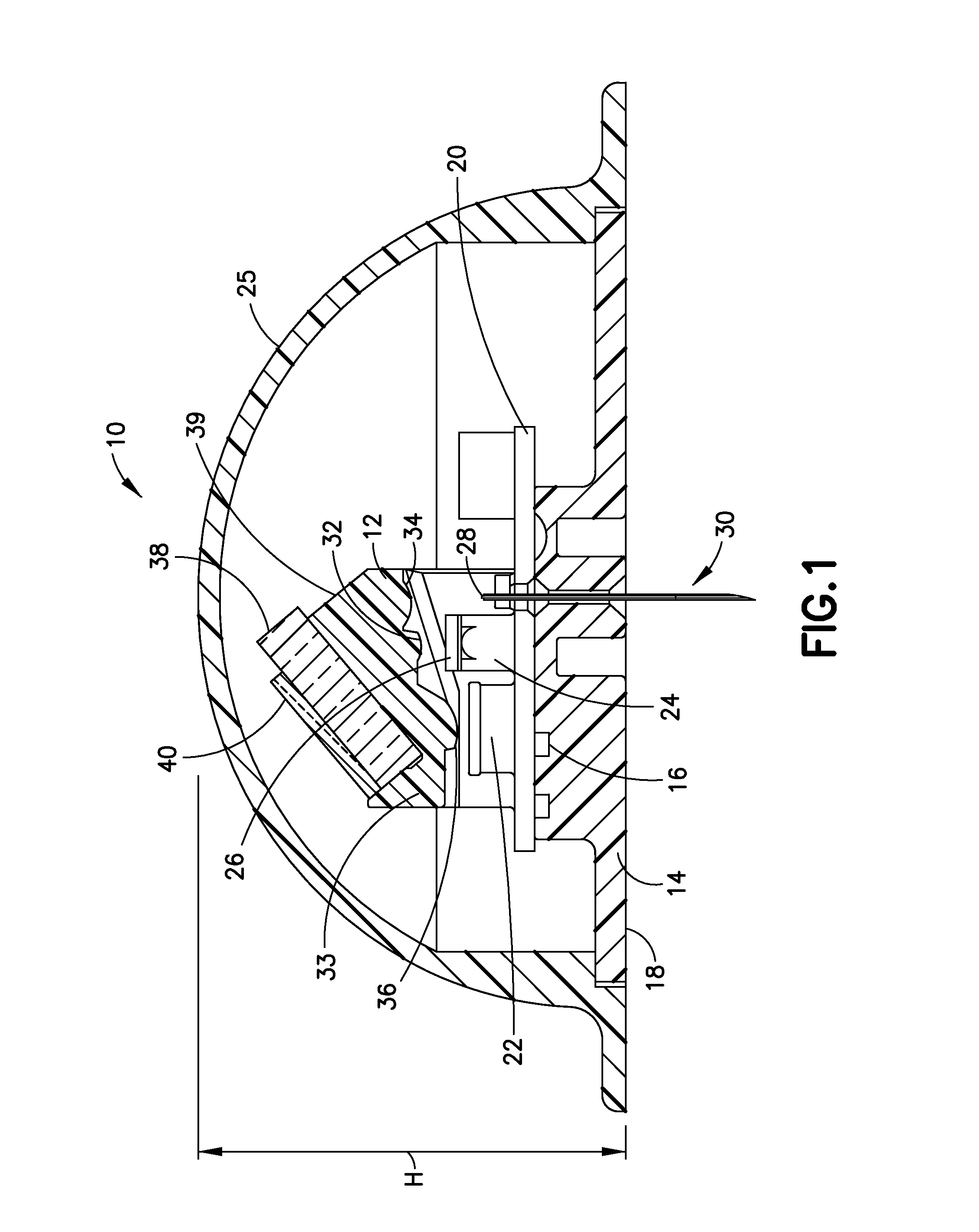
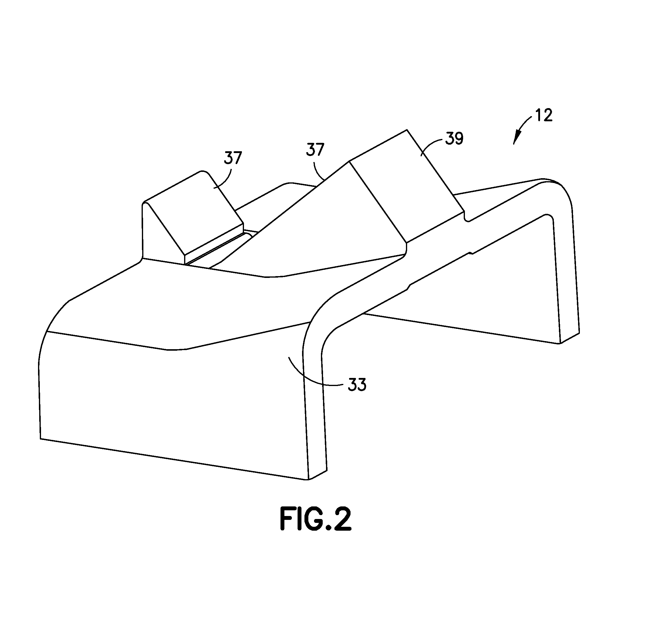
[0033]In an illustrative embodiment according to the present invention, a continuous monitoring device is used in identifying an analyte, such as glucose in blood or interstitial fluid (ISF), using a biomaterial, such as glucose binding protein (GBP), that is brought into contact with the analyte. The continuous monitoring device includes a light source for emitting light used to illuminate the biomaterial. Light is emitted from the light source and reflected by an optical coupler and transmitted to the biomaterial via a fiber. The bi...


PUM

PropertyMeasurementUnit
heightaaaaaaaaaa
heightaaaaaaaaaa
fluorescentaaaaaaaaaa

Abstract

Optical systems are disclosed for use in identifying an analyte, such as glucose in blood or interstitial fluid (ISF), using a biomaterial, such as glucose binding protein (GBP), that is brought into contact with the analyte. An optical system includes a first filter adapted to reflect light emitted from a light-emitting diode to illuminate a fluorescent body, and further adapted to transmit light emitted from the fluorescent body, and a second filter adapted to separate light transmitted by the first filter into signal band light and reference band light.

Description

CROSS-REFERENCE TO RELATED APPLICATION[0001]This application claims the benefit under 35 U.S.C. §119 (e) of U.S. Provisional Application No. 61 / 755,296, filed on Jan. 22, 2013, in the U.S. Patent and Trademark Office, the disclosure of which is incorporated herein by reference in its entirety.FIELD OF THE INVENTION[0002]The present invention relates generally to continuous glucose monitoring (CGM) devices, and more particularly, to optical couplers used to direct excitation light from a light-emitting diode (LED) into a fiber to illuminate or fluoresce a glucose binding protein (GBP) and then transmit the light emitted from the GBP to photodiode detectors.BACKGROUND OF THE INVENTION[0003]In patients with diabetes, glucose levels need to be monitored to maintain a healthy balance of glucose in the body. Glucose levels can be monitored by GBP coated sensors such as on-body CGM devices. On-body CGM devices generally include a light source used to illuminate or fluoresce GBP within a pa...

Claims


Application Information

Patent Timeline
Patent Type & Authority Applications(United States)
IPC IPC(8): A61B5/1455A61B5/145G01N21/64
CPCA61B5/1455G01N21/6486A61B2562/0233G01N2201/062G01N2201/08A61B5/14532G01N21/645A61B5/0071A61B5/1459A61B5/1545
Inventor WEBER, AARONTRACEY, DAVIDSALEMME, JAMESPRUDDEN, JOHN
Owner EMBECTA CORP
Why Eureka
Try Eureka