Processes for producing hydrogen cyanide using static mixer

a technology of hydrogen cyanide and static mixer, which is applied in the direction of manufacturing tools, transportation and packaging, cooking vessels, etc., can solve the problems of affecting the economics of hcn manufacturing, affecting the ability of manufacturers to meet the needs of customers, and affecting the production efficiency of hcn

Inactive Publication Date: 2015-12-10
INVISTA NORTH AMERICA R L
View PDF5 Cites 8 Cited by
  • Summary
  • Abstract
  • Description
  • Claims
  • Application Information

AI Technical Summary

Benefits of technology

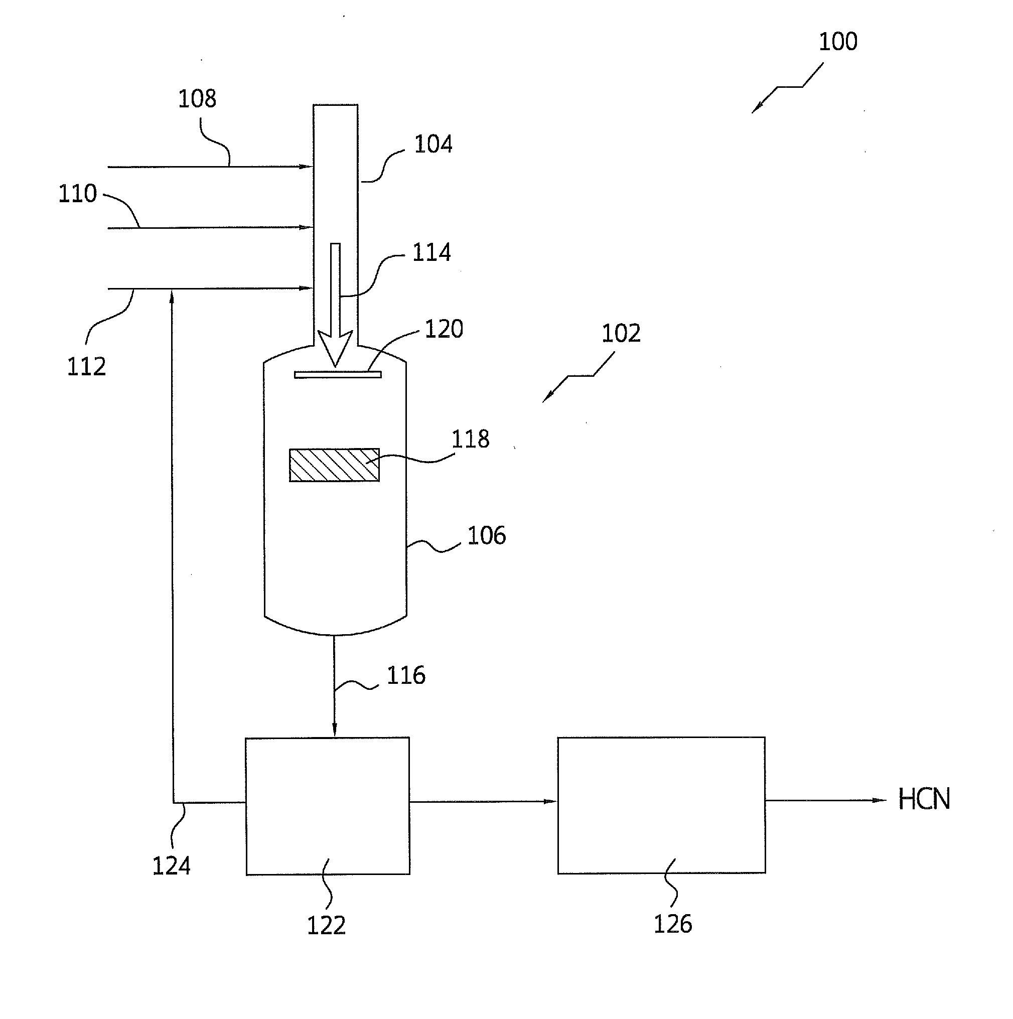
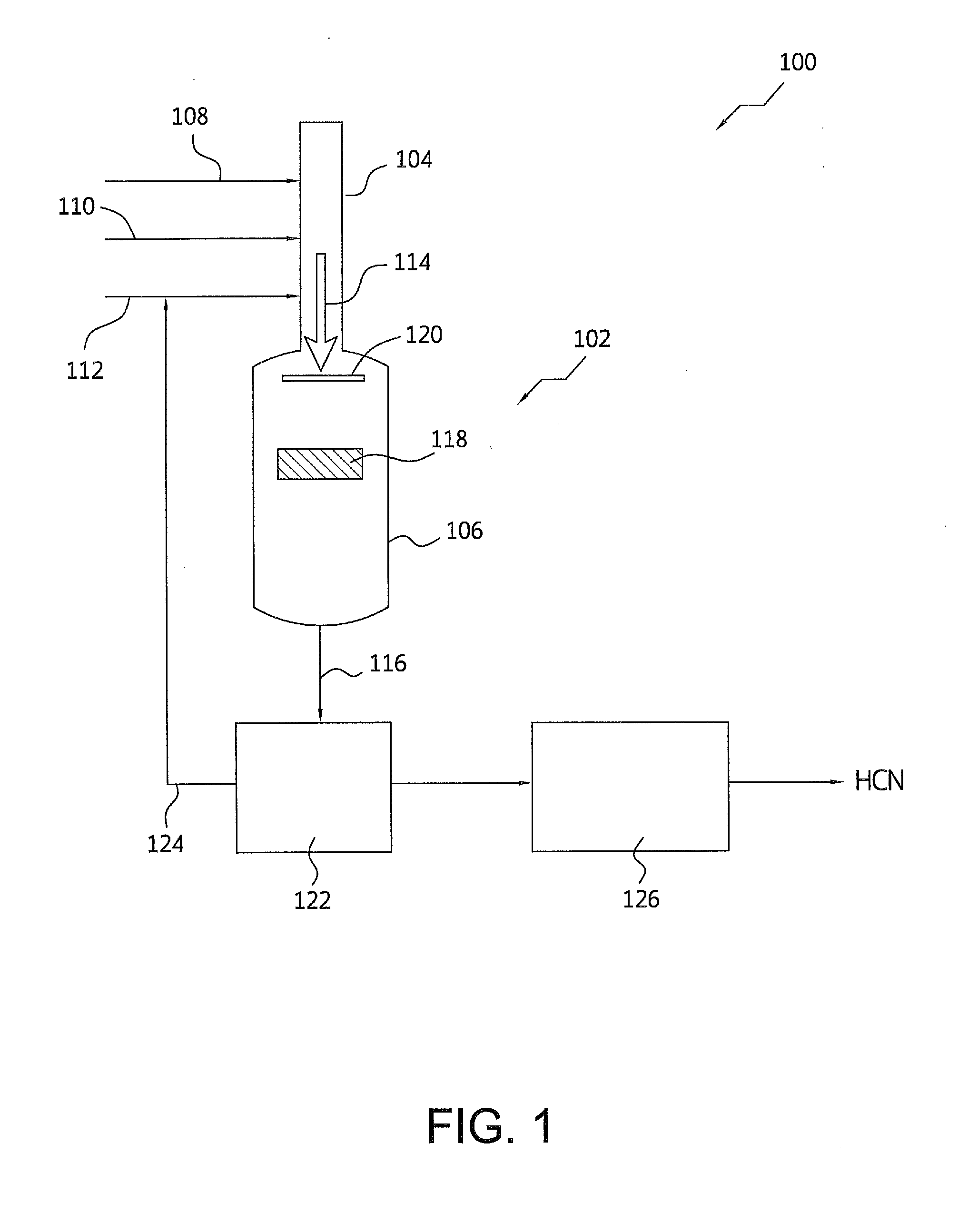
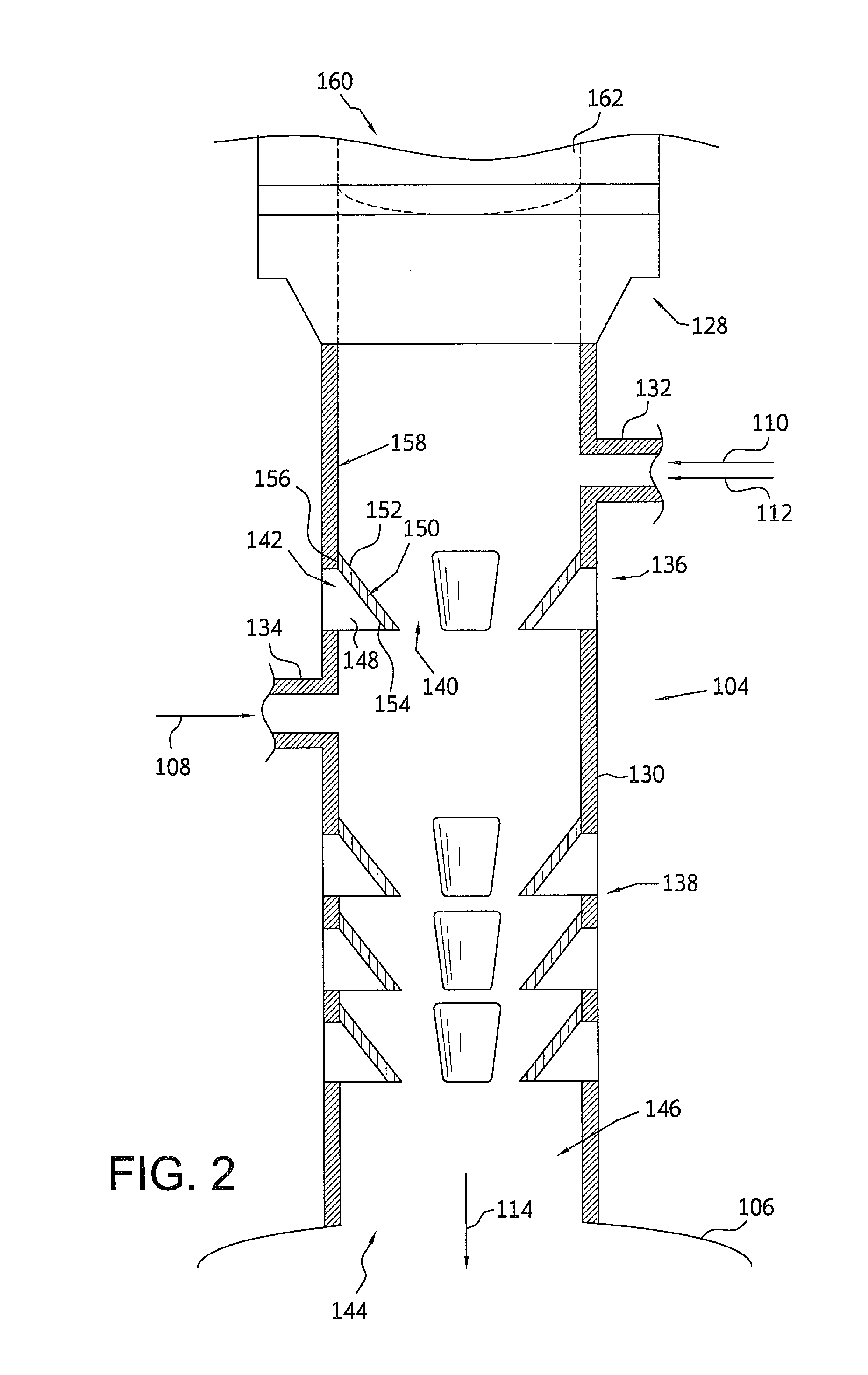
[0009]In a first embodiment, the present invention is directed to a reaction assembly for preparing hydrogen cyanide comprising: (a) a mixing vessel comprising an elongated conduit having an outlet located at a proximal end of the elongated conduit, a first inlet port and a second inlet port each for introducing at least one reactant gas selected from the group consisting of a methane-containing gas, an ammonia-containing gas, an oxygen-containing gas, and mixtures thereof, into the mixing vessel, wherein the second inlet port is downstream of the first inlet port, a first static mixing zone comprising one or more first rows of non-continuous slots through which one or more corresponding tabs are inserted and secured to an external surface of the elongated conduit, and wherein the first static mixing zone is adjacent to the first inlet port, a second static mixing zone comprising one or more second rows of non-continuous slots through which one or more corresponding tabs are inserted and secured to the external surface of the elongated conduit, and wherein the second static mixing zone is adjacent to the second inlet port, wherein each corresponding tab has an upstream face that is angled in the flow direction, wherein the first and second static mixing zones provide cross-stream mixing of the at least one reactant gas to produce a ternary gas; and (b) a reactor vessel comprising a reactor inlet that is operatively coupled to the outlet to receive the ternary gas mixture, and a catalyst bed containing a catalyst for producing a hydrogen cyanide stream. The number of rows in the first static mixing zone may be from one to ten and the number of rows in the second static mixing zone may be from one to ten. Each of the first rows and second rows may contain from one to ten of the non-continuous slots. The number of rows in the second static mixing zone may be greater than or equal to the number of rows in the first static mixing zone. The corresponding tabs may have an angle from an internal wall of the conduit from 5° to 45°. The reaction assembly may further comprise one or more flow straighteners located upstream of the first static mixing zone for aligning the flow of the at least one reactant gas, wherein the one or more flow straighteners each have a center body. The reaction assembly may further comprise one or more flow straighteners located upstream of the second static mixing zone for aligning the flow of the at least one reactant gas, wherein the one or more flow straighteners each have a center body. The non-continuous slots may be an I-shape, I-shape, T-shape, U-shape, or V-shape. The non-continuous slots of two or more first rows may be transversely aligned. The non-continuous slots of two or more second rows may be transversely aligned. Each of the corresponding tabs within the elongated conduit may be non-parallel to the flow direction. Each of the corresponding tabs may have a trailing edge having an angle from 30° to 90°. Each of the corresponding tabs may have a degree of cant from 0° to 7°. Each of the corresponding tabs may have a surface area from 50 to 250 cm2. Each of the corresponding tabs may comprise 310SS S or 316SS.
[0010]A second embodiment of the present invention is directed to a reaction assembly for preparing hydrogen cyanide comprising (a) a mixing vessel comprising an elongated conduit having an outlet located at a proximal end of the elongated conduit, a first inlet port and a second inlet port each for introducing at least one reactant gas selected from the group consisting of a methane-containing gas, an ammonia-containing gas, an oxygen-containing gas, and mixtures thereof, into the mixing vessel, wherein the second inlet port is proximal to the first inlet port, a first static mixing zone comprising one or more first rows of non-continuous slots through which one or more corresponding tabs at having a first angle are inserted and secured to an external surface of the elongated conduit, and wherein the first static mixing zone is adjacent to the first inlet port, a second static mixing zone comprising one or more second rows of non-continuous slots through which one or more corresponding tabs having a second angle are inserted and secured to the external surface of the elongated conduit, and wherein the second static mixing zone is adjacent to the second inlet port and/or proximal to the second inlet port, wherein the first angle is different than the second angle, wherein the first and second static mixing zones provide cross-stream mixing of the at least one reactant gas to produce a ternary gas; and (b) a reactor vessel comprising a reactor inlet that is operatively coupled to the outlet to receive the ternary gas mixture, and a catalyst bed containing a catalyst for producing a hydrogen cyanide stream. The first angle and the second angle may be from 5° to 45°. The first angle is 30° and may be larger than the second angle. The first angle is 30° and may be less than the second angle.
[0011]A third embodiment of the present invention is directed to a process for producing hydrogen cyanide, comprising: introducing a methane-containing gas, an ammonia-containing gas, and an oxygen-containing gas into an elongated conduit to produce a ternary gas mixture, the elongated conduit comprising one or more static mixing zones having at least one non-continuous slot through which a tab is inserted and secured to an external surface of the elongated conduit; and contacting the ternary gas mixture with a catalyst in a catalyst bed to provide a reaction product comprising hydrogen cyanide. The step of introducing may comprise: mixing the methane-containing gas and the ammonia-containing gas in a first static mixing zone comprising one or more first rows of the non-continuous slots to form a binary gas mixture; and mixing the oxygen-containing gas with the binary gas mixture in a second static mixing zone to form the ternary gas mixture, wherein the second static mixing zone comprises one or more second rows of the non-continuous slots. The ternary gas mixture may have a coefficient of variation of

Problems solved by technology

Additionally, emissions of HCN production processes from production facilities may be subject to regulations, which may affect the economics of HCN manufacturing.
However, when carrying out the prior mixing of the reactive gases, the risks associated with the reactivity of the gases may become apparent.
These previous mixing chambers for HCN producti

Method used


Image

  • Processes for producing hydrogen cyanide using static mixer
  • Processes for producing hydrogen cyanide using static mixer
  • Processes for producing hydrogen cyanide using static mixer

Examples


example 1

[0089]As illustrated in FIG. 2, a plurality of tabs having an I-shape support are inserted through corresponding non-continuous slots on an elongated conduit to form one row of four tabs in a first static mixing zone and three rows of four tabs in a second static mixing zone to form the mixing vessel. The first static mixing zone is positioned between the inlet port of the methane and ammonia containing gas and the second static mixing zone is positioned between the inlet port of the oxygen-containing gas and outlet port. Each tab has an angle of 30°±1°, except for the bottom row in the second static mixing zone where the tabs have an angle of 25°±1°. Each tab has a surface area that is approximately 77.5 cm2. Each tab is inserted from the inside of the elongated conduit and is welded to the external surface of the elongated conduit. Tabs from one row align with the adjacent rows and tabs from the first mixing zone align with tabs from the second mixing zone. The degree of cant of t...

example 2

[0092]Methane and ammonia-containing reactant gases are fed to the first static mixing zone and oxygen-containing reactant gas is fed to the second static mixing zone. The reactant gases are fed at an methane-to-oxygen molar ratio of 1.2 and an ammonia-to-oxygen molar ratio of 1:1.5 to produce a ternary gas mixture containing approximately 28.5 vol. % oxygen. The ternary gas mixture is then fed to a reactor vessel having a 85 / 15 platinum / rhodium catalyst on a flat catalyst bed. The reaction temperature is from 1000° C. to 1200° C. Using the exemplary mixing vessel of Example 1, the ternary gas mixture has a coefficient of variation (CoV) of less than 0.1 across the catalyst bed. The operating pressure of the static mixer may vary from 130 kPa to 400 kPa. In addition, pressure drop within the exemplary mixing vessel of Example 1 is less than 35 kPa.

example 3

[0093]Using the exemplary mixing vessel of Example 1 and under similar reaction conditions as Example 2, the catalyst bed has a bed temperature variation from 15° C. to 25° C. across the bed. This bed temperature variation would indicate a thoroughly mixed ternary gas mixture. In contrast, the static mixer of Comparative A, under similar reaction conditions as Example 2, produces a ternary gas mixture that would result in a bed temperature variation of 35 to 100° C. across the bed. Poor mixing of the static mixer of Comparative A may be attributed to the difficultly in aligning tabs by welding to the inside of elongated conduit.


PUM

PropertyMeasurementUnit
Temperatureaaaaaaaaaa
Angleaaaaaaaaaa

Abstract

A static mixer is disclosed for a hydrogen cyanide reaction process that thoroughly mixes the reactant gases to form a ternary gas mixture that has a coefficient of variation of less than 0.1 across the diameter of the catalyst bed. The static mixer comprises tabs that are inserted through non-continuous slots in the conduit and the tabs are secured to the external wall of the conduit.

Description

CROSS REFERENCE TO RELATED APPLICATION[0001]This application claims priority to U.S. App. No. 61 / 738,657, filed Dec. 18, 2012, the entire contents and disclosures of which are incorporated herein.FIELD OF THE INVENTION[0002]The present invention relates to a process for producing hydrogen cyanide and more particularly, to a static mixer for producing a thoroughly mixed ternary gas that is contacted with a catalyst, and to processes for using the static mixer and manufacturing the same.BACKGROUND OF THE INVENTION[0003]Conventionally, hydrogen cyanide (“HCN”) is produced on an industrial scale according to either the Andrussow process or the BMA process. (See e.g., Ullman's Encyclopedia of Industrial Chemistry, Volume A8, Weinheim 1987, pages 161-163). For example, in the Andrussow process, HCN can be commercially produced by reacting ammonia with a methane-containing gas and an oxygen-containing gas at elevated temperatures in a reactor in the presence of a suitable catalyst (U.S. Pa...

Claims


Application Information

Patent Timeline
IPC IPC(8): C01C3/02B23K28/00B01F15/00B01F23/10
CPCC01C3/0225C01C3/0212Y10T29/49828B23K28/00B01F15/00922C01C3/022B01F23/10B01F25/311B01F25/31423B01F25/3141B01F25/43161B01F25/431971B01F35/10
Inventor CATON, JOHN C.RABENALDT, DAVID W.MCKNIGHT, WILLIAM A.
Owner INVISTA NORTH AMERICA R L
Why Eureka
Try Eureka