Method for forming a thermoelectric film having a micro groove

a thermoelectric film and micro groove technology, applied in the manufacture/treatment of thermoelectric devices, basic electric elements, electrical appliances, etc., can solve the problems of nano-scaled catalyst residual on the tips of grown nano wires, and the diameter of individual nano wires can vary in a wild manner

Inactive Publication Date: 2015-12-10
NAT CENT UNIV
View PDF1 Cites 1 Cited by
  • Summary
  • Abstract
  • Description
  • Claims
  • Application Information

AI Technical Summary

Benefits of technology

[0014]The prepared thermoelectric films have micro grooves having uniform diameters because the initially formed sacrificing wires are highly uniform in diameter. Further, there will be no catalyst

Problems solved by technology

The drawback of such VLS method is that there will be nano-scaled catalyst residual remained on the tips on the grown nano wire.
Howev

Method used


Image

  • Method for forming a thermoelectric film having a micro groove
  • Method for forming a thermoelectric film having a micro groove
  • Method for forming a thermoelectric film having a micro groove

Examples


Embodiment Construction

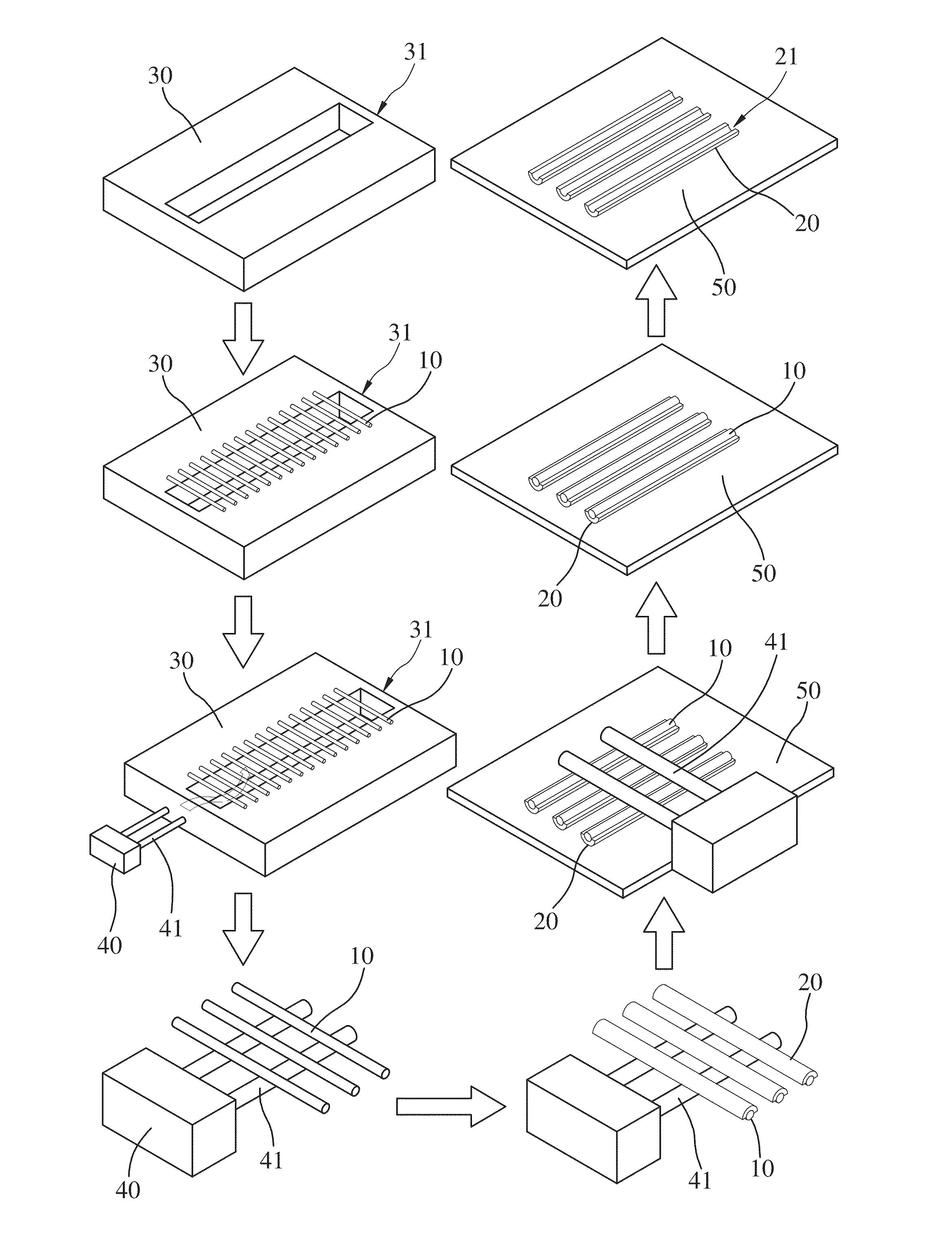
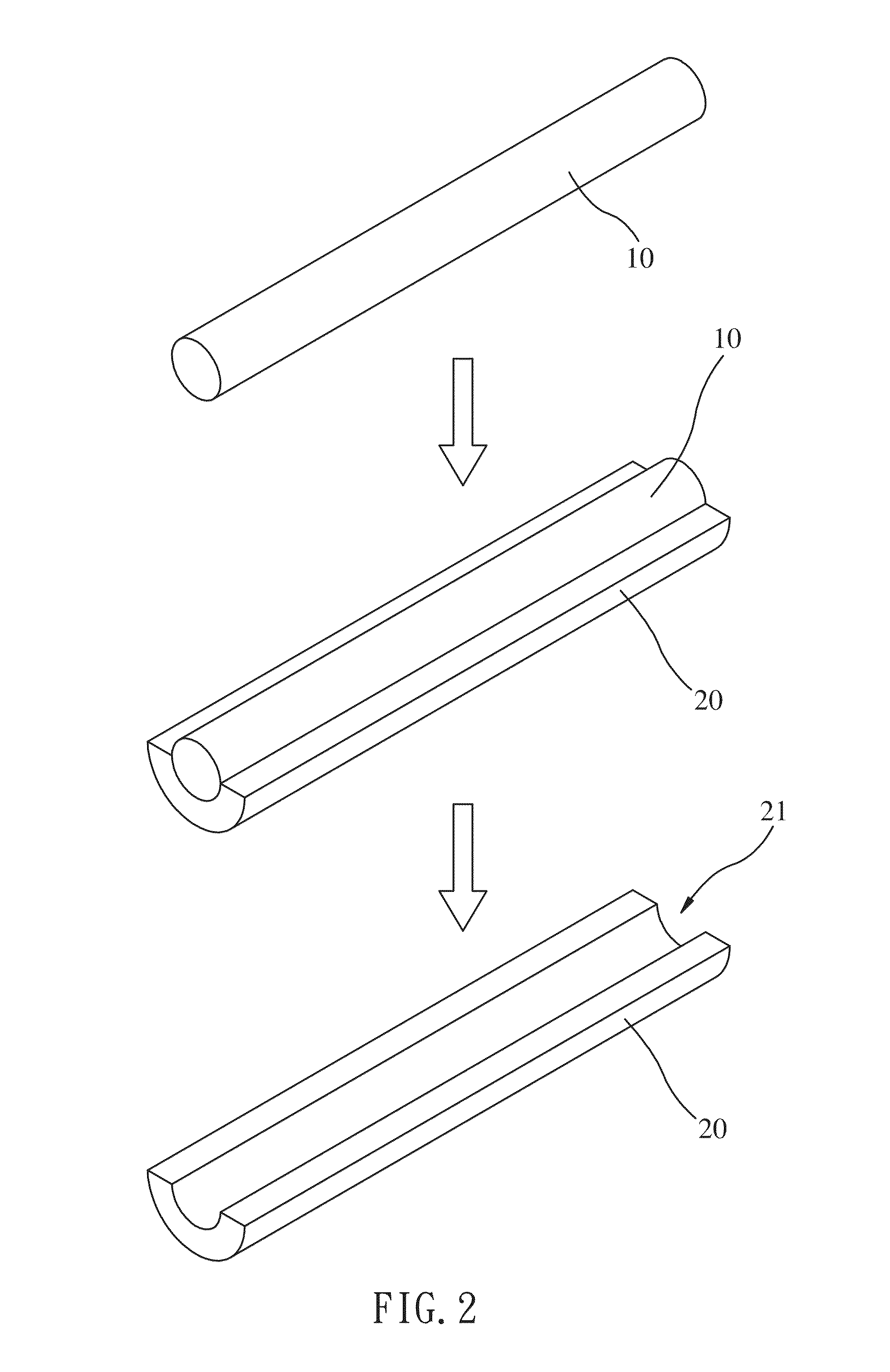
[0020]Please refer to FIGS. 1 and 2. The present invention provides a method of forming a thermoelectric film 20 having a micro groove 21. The thermoelectric film 20 has a radio side open to the surroundings. In other words, the thermoelectric film 20 is laterally open on one side and does not form a tube. The method of forming the thermoelectric film includes the following steps:

[0021]A) forming a plurality of parallel sacrificing wires 10 by electrospinning. A diameter of each sacrificing wire 10 is 100-500 nm. If the diameter of the sacrificing wire 10 were smaller than 100 nm, the sacrificing wire 10 might not be made easily. If the diameter thereof were bigger than 500 nm, the thermoelectric properties of later formed thermoelectric film 20 could not be efficiently improved. The aforementioned electrospinning is a means using an electrical charge to draw fine fibers from a liquid. During electrospinning, high voltage is applied to a metal needle filled with sacrificing material...


PUM


Abstract

A method for forming a thermoelectric film having a micro groove includes the following steps: A) forming a plurality of parallel sacrificing wires by electrospinning, a diameter of each sacrificing wire being 100-500 nm; B) coating a thermoelectric film having a thickness of 80-200 nm on a part of a surface of each sacrificing wire; and C) removing the sacrificing wires from the thermoelectric films and thus obtaining the thermoelectric films each having the micro groove, a radio side of each thermoelectric film being open to the surroundings. The thermoelectric films finally prepared can have higher size uniformity without the disadvantage of catalyst residual. Further, the thermoelectric films each have a size smaller than the mean free path of phonons in one dimension, and thus the thermoelectric properties of the thermoelectric films can be improved.

Description

BACKGROUND OF THE INVENTION[0001]1. Field of the Invention[0002]The present invention relates generally to a method of forming a thermoelectric film, and more specifically to a method of forming a thermoelectric film having a micro groove.[0003]2. Description of the Related Art[0004]Fossil fuels are currently the primary sources of energy consumption in the world. Owing to the nonrenewable characteristics of fossil fuels, people are dedicated to find other renewable energies and to reuse waste energies such as waste heat including industrial heat, vehicle-emitted heat and environmental heat. If these waste heat can be reused properly, the dependency on fossil fuels can be lowered and the consumption of fossil fuels can be mitigated.[0005]Some thermoelectric materials have been recognized and can convert heat energy into electricity directly. If the thermoelectric material has a size smaller than the mean free path of phonons and larger than that of the electrons in one or more dimen...

Claims


Application Information

Patent Timeline
IPC IPC(8): H01L35/34
CPCH01L35/34H10N10/01
Inventor LEE, SHENG-WEINIU, YI-FANLI, PEI-WENHSIN, CHENG-LUNTSENG, CHUNG-JEN
Owner NAT CENT UNIV
Why Eureka
Try Eureka