Biomolecule measuring device

a biomolecule and measuring device technology, applied in the direction of measuring devices, instruments, scientific instruments, etc., can solve the problems of increasing the measurement time, no method is discussed preferable for biomolecule measuring devices, and only increasing the threshold voltage by hot electron injection, etc., to achieve the effect of reducing the measurement nois

Active Publication Date: 2015-12-17
HITACHI HIGH-TECH CORP
View PDF5 Cites 4 Cited by
  • Summary
  • Abstract
  • Description
  • Claims
  • Application Information

AI Technical Summary

Benefits of technology

[0020]With the biomolecule measuring device according to the present invention, it is possible to effectively reduce measurement noises occurring when measuring biomolecule samples using semiconductor sensors that detect ion concentrations.

Problems solved by technology

This causes a technical problem of increased measuring time.
However, no method is discussed preferable for biomolecule measuring devices in which a plurality of ISFETs is arranged in arrayed manner.
In addition, hot electron injection only works for increasing the threshold voltage.
However, in case of semiconductor sensor array in which a lot of ISFETs is allocated in arrayed manner, it is necessary to calibrate for each data from vast amount of ISFETs, which is impractical.
Thus a lot of time is required from the beginning of measurement until acquiring the result.
Further, in order to precisely estimate backgrounds across wide value range, huge amount of data is required.

Method used


Image

  • Biomolecule measuring device
  • Biomolecule measuring device
  • Biomolecule measuring device

Examples


embodiment 1

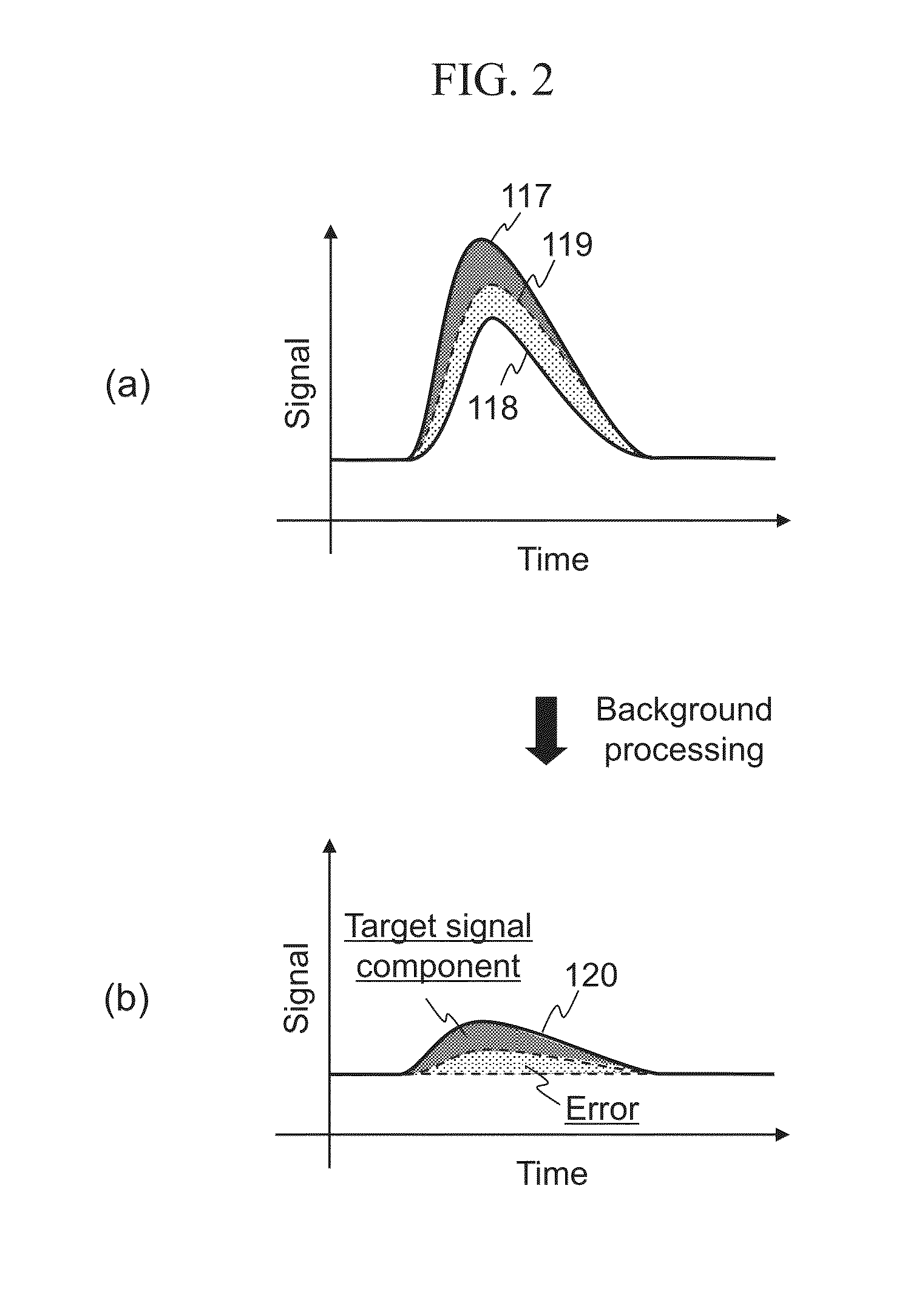
[0093]As discussed thus far, the biomolecule measuring device according to the embodiment 1 generates a trigger for the reagent solution 108 to react using the heater 308 or other alternative means, after the solution sender 303 starts transmitting the reagent solution 108 or more preferably after the solution sender 303 completes transmission of the reagent solution 108. Accordingly, it is possible to temporally separate the incorporation signal 1302 from the background as shown in FIG. 10, thereby readily extracting the incorporation signal 1302 only.

[0094]The biomolecule measuring device according to the embodiment 1 includes a circuit that fixes the drain current of ISFET 114 at Id and that fixes the source-drain voltage Vds at VAB. Accordingly, as shown in Equation 3, it is possible to extract only the threshold variation ΔVth of the ISFET 114 from the output terminal Ok.

[0095]The biomolecule measuring device according to the embodiment 1 is capable of subtracting the drift and...

embodiment 2

[0107]As discussed thus far, the biomolecule measuring device according to the embodiment 2 includes the transistor 1500 that turns ON / OFF the connection between the floating gate 102 and the voltage source. The biomolecule measuring device turns ON the transistor 1500 before measuring the incorporation signal 1302 to reset the noises. Accordingly, the process for subtracting the noise components is not necessary, thereby reducing the computational loads of the data processor 311. In addition, it is possible to decrease the dynamic range of A / D converter and amount of data.

[0108]The embodiment 2 outputs the incorporation event trigger to measure the incorporation signal 1302 after resetting the noises using the transistor 1500. However, even if the incorporation event trigger is not used, it is possible to cancel the drift and offset component 1301 using the transistor 1500. In this case, the temperature sensor 307, the heater 308, and the cooler 300 are not necessary, thereby simpl...

embodiment 3

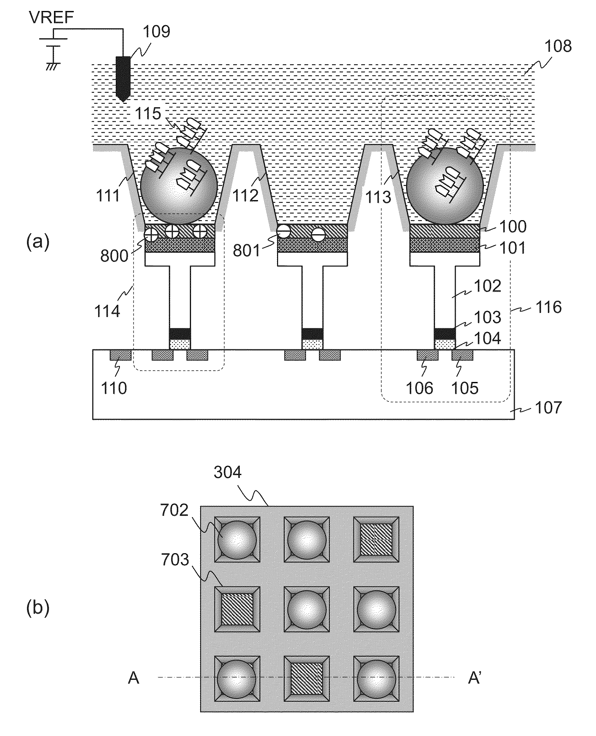
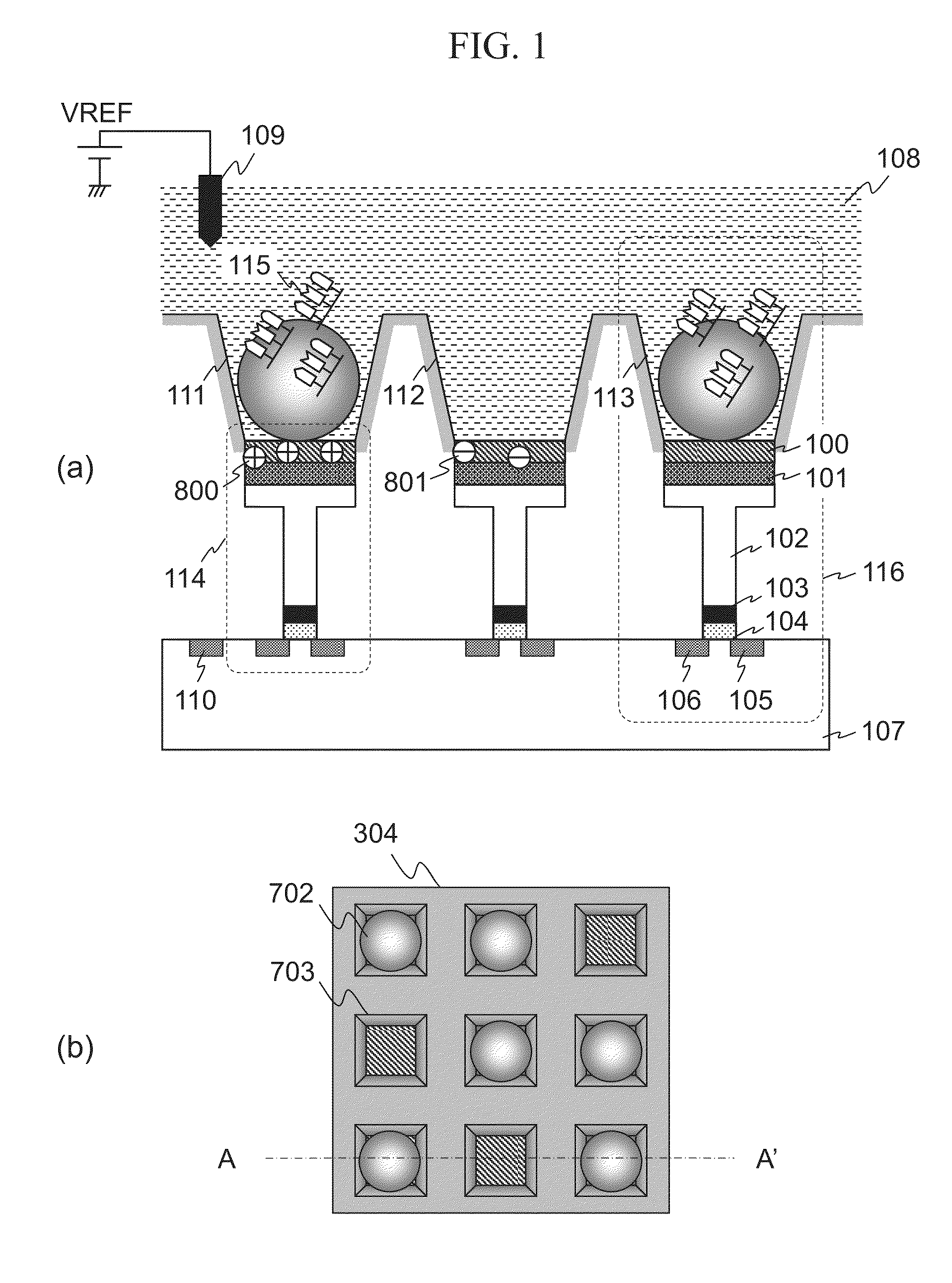
[0123]As discussed thus far, the biomolecule measuring device according to the embodiment 3 separates each of the wells 703 from each other to prevent the signal components from interfering between adjacent wells 703 due to cross talks. Thus it is possible to improve the signal quality of the ISFET 114.

[0124]The present invention is not limited to the embodiments, and various modified examples are included. The embodiments are described in detail to describe the present invention in an easily understood manner, and the embodiments are not necessarily limited to the embodiments that include all configurations described above. Part of the configuration of an embodiment can be replaced by the configuration of another embodiment. The configuration of an embodiment can be added to the configuration of another embodiment. Addition, deletion, and replacement of other configurations are also possible for part of the configurations of the embodiments.

[0125]For example, the embodiments 1-3 de...


PUM

PropertyMeasurementUnit
threshold voltagesaaaaaaaaaa
voltageaaaaaaaaaa
voltageaaaaaaaaaa

Abstract

Provided is a biomolecule measuring device capable of effectively reducing measurement noise occurring when measuring a biomolecule sample using a semiconductor sensor. This biomolecule measuring device generates a trigger to react a sample with a reagent after starting to send the reagent onto the semiconductor sensor that detects ion concentration (see FIG. 7).

Description

TECHNICAL FIELD[0001]The present invention relates to a biomolecule measuring device.BACKGROUND ART[0002]In recent years, biomolecule measuring devices using semiconductor technologies are drawing attentions. Patent Literature 1 listed below describes a DNA sequencer that cost-effectively and rapidly determines base sequences of deoxyribo nucleic acid (DNA) using pH sensor arrays manufactured with semiconductor technologies. Semiconductor sensors quantify reactions of target biomaterials according to magnitude of electrical signals. Therefore, semiconductor sensors do not require conventional expensive fluorescent reagents and thus are advantageous in terms of costs. It is possible to integrate millions to more than a billion sensors using semiconductor micro-processing technologies. It is also possible to activate each of such sensors in parallel to perform measurements. Therefore, the throughput of the measurement may be readily improved.[0003]Ion Sensitive Field Effect Transistor...

Claims


Application Information

Patent Timeline
Patent Type & Authority Applications(United States)
IPC IPC(8): G01N27/414
CPCG01N27/4145
Inventor YANAGAWA, YOSHIMITSUYOKOI, TAKAHIDEITABASHI, NAOSHIKAWAHARA, TAKAYUKIMIGITAKA, SONOKOYOSHIDA, MAKIKOMURAMATSU, TAKAMICHI
Owner HITACHI HIGH-TECH CORP
Why Eureka
Try Eureka