Gravity Induced Separation Of Gases And Fluids In A Vacuum-Based Drilling Fluid Recovery System

Inactive Publication Date: 2015-12-24
FP MARANGONI INC
View PDF0 Cites 3 Cited by
  • Summary
  • Abstract
  • Description
  • Claims
  • Application Information

AI Technical Summary

Benefits of technology

[0062]In certain embodiments, a fluid separator is provided in the vacuum conduit between the hydrostatic c

Problems solved by technology

The loss of drilling fluids presents several technological and cost challenges to the energy exploration industry.
These challenges generally include the seepage losses of drilling fluids to the formation, the recovery of drilling fluids at surface and/or the disposal of drilling detritus or cuttings that are contaminated with drilling fluid.
With some drilling fluids having values in excess of $1600 per cubic meter, the loss of such volumes of fluids represents a substantial cost to drill operators.
Additionally, in some areas the delivery of oil or water for the formulation of drilling fluids can present several costly challenges for some operations; specifically desert, offshore and even some districts where communities will not allow allocation of water for this use.
As noted above, one particular problem is the separation of drilling fluid and any hydrocarbons from the formation that may be adhered to the drill cuttings (collectively “fluids”) at the surface.
As known to those skilled in the art, these devices are typically rented by operators at costs ranging from $1000 to $2000 per day and, as a result, can also represent a significant cost to operators.
In addition, an operator will likely also factor in the environmental effects and/or costs of disposal of drilling fluid contaminated drill cuttings in designing their drilling fluids/drill cutting separation/recovery systems.
However, these techniques have generally been unable to be cost effective for many drilling fluids as the use of diluting fluids often produces unacceptable increases in drilling fluid volume and/or changes in chemical consistency and, hence, rheological properties of the drilling fluid.
Thus, while various separation systems are often effective and/or efficient in achieving a certain level of fluids/cuttings separations, each form of separation technology can generally only be efficiently operated within a certain range of conditions or parameters and at particular price points.
That is, while an operator may be able to lower the fluids retained on cuttings coming off the shaker with a larger mesh screen (50-75 mesh), the problem with a larger mesh screen is that substantially greater quantities of solids will pass through the screen, that then significantly affect the rheology and density of the recovered fluids and/or require the use of an additional and potentia

Method used


Image

  • Gravity Induced Separation Of Gases And Fluids In A Vacuum-Based Drilling Fluid Recovery System
  • Gravity Induced Separation Of Gases And Fluids In A Vacuum-Based Drilling Fluid Recovery System
  • Gravity Induced Separation Of Gases And Fluids In A Vacuum-Based Drilling Fluid Recovery System

Examples


example embodiments

DESCRIPTION OF EXAMPLE EMBODIMENTS

[0073]Various aspects of the invention will now be described with reference to the figures. For the purposes of illustration, components depicted in the figures are not necessarily drawn to scale. Instead, emphasis is placed on highlighting the various contributions of the components to the functionality of various aspects of the invention. A number of possible alternative features are introduced during the course of this description. It is to be understood that, according to the knowledge and judgment of persons skilled in the art, such alternative features may be substituted in various combinations to arrive at different embodiments of the present invention.

example 1

Drill Fluid Recovery System with Primary Fluid Recovery Driven by a Hydrostatic Chamber

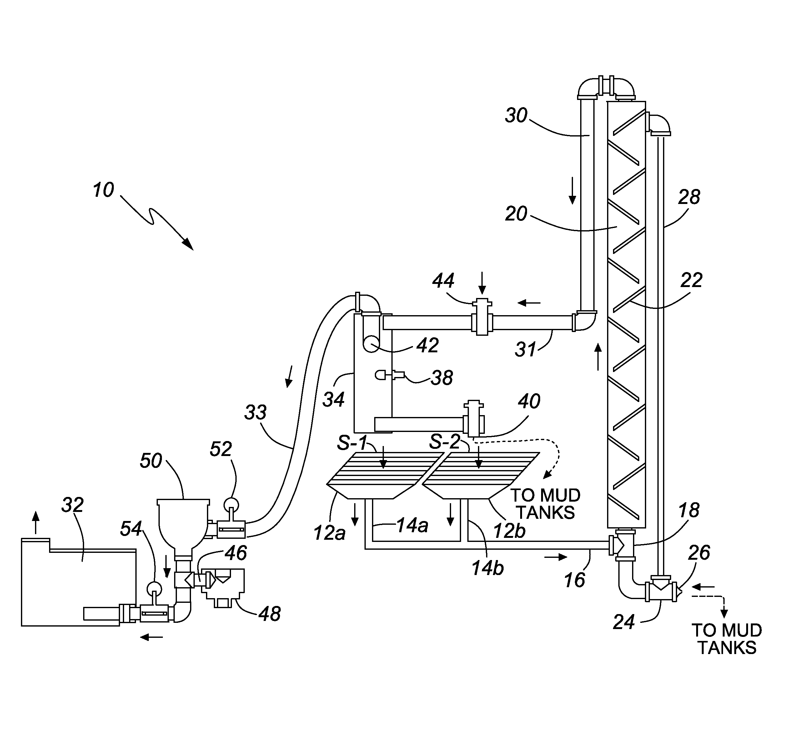
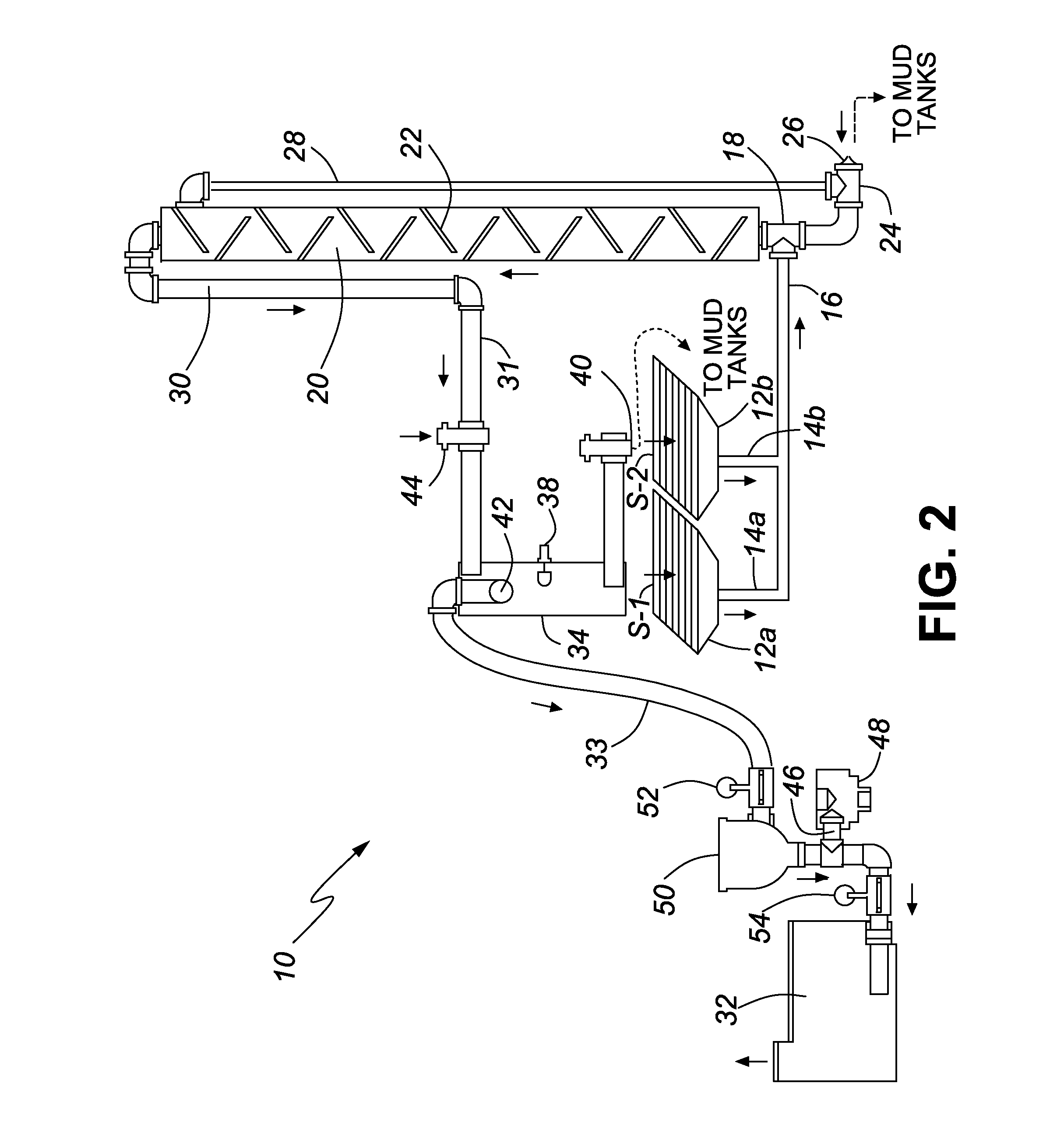
[0074]Referring now to FIG. 2, there is shown a system 10 according to one embodiment of the present invention. System 10 is shown connected to two shaker screens S-1 and S-2. Alternative embodiments include only a single connection to a single screen or more than two connections to more than two screens. These alternatives are within the scope of the invention. The connections to the screens S-1 and S-2 are made with vacuum screen attachments 12a and 12b which are often referred to in the art as “manifolds” or “vacuum manifolds.” The function of these components is to convey downward vacuum force against the fluid-contaminated drill cuttings on the screens S-1 and S-2, thereby removing the fluid from the cuttings which continue to vibrate on the shaker as they are conveyed off the screens S-1 and S-2. Vacuum screen attachments 12a and 12b are connected to respective vacuum conduits 14a and 14b wh...

example 2

Drill Fluid Recovery System with Primary Fluid Recovery Driven by an Air Distribution and Fluid Dump Assembly and Secondary Fluid Recovery Driven by a Hydrostatic Chamber

[0083]In accordance with another embodiment of the present invention and with reference to FIG. 3, there is shown another system 100 for recovering drilling fluid from drill cuttings. System 100 has many features similar to the features of the embodiment shown in FIG. 2 and therefore similar reference numerals are used in the ensuing description of operation of this system. The main difference between system 10 (FIG. 2) and system 100 (FIG. 3) is that system 100 is provided with a conduit connector unit which is herein described as the “air distribution and fluid dump assembly.” The air distribution and fluid dump assembly 15 is connected to vacuum conduits 14a and 14b and to vacuum conduit 16 which leads to the hydrostatic chamber 20. It is to be understood that the structure of the air distribution and fluid dump ...


PUM

PropertyMeasurementUnit
Weightaaaaaaaaaa
Timeaaaaaaaaaa
Forceaaaaaaaaaa

Abstract

A system for recovering used drilling fluid from drill cuttings being processed on a shaker screen. The system includes: a vacuum screen attachment operatively connected to the underside of the shaker screen, the vacuum screen attachment operatively connected to a vacuum source by a vacuum conduit; a hydrostatic chamber located in the vacuum conduit downstream of the vacuum screen attachment, the hydrostatic chamber having a fluid dump port at or adjacent to its bottom surface; a means for setting a limit of fluid accumulation in the hydrostatic chamber, wherein fluid dumps from the fluid dump port when the limit of fluid accumulation is reached; and a conduit for conveying the fluid dumped from the fluid dump port to a storage tank.

Description

CROSS-REFERENCE TO RELATED APPLICATIONS[0001]This application claims priority from U.S. Provisional Application Ser. No. 62 / 014,781 filed on Jun. 20, 2014, and U.S. Provisional Application Ser. No. 62 / 034,309 filed on Aug. 7, 2014, the entire disclosures of which are incorporated herein by reference.FIELD OF THE INVENTION[0002]The invention relates to systems and methods for recovering used drilling fluids from drill cuttings generated by oil and gas drilling operations.BACKGROUND OF THE INVENTION[0003]The loss of drilling fluids presents several technological and cost challenges to the energy exploration industry. These challenges generally include the seepage losses of drilling fluids to the formation, the recovery of drilling fluids at surface and / or the disposal of drilling detritus or cuttings that are contaminated with drilling fluid. In the context of this description, “drilling fluid” is both fluid prepared at surface used in an unaltered state for drilling as well as all fl...

Claims


Application Information

Patent Timeline
IPC IPC(8): B01D29/60B01D29/50B01D36/00B01D29/085
CPCB01D29/605B01D36/00B01D29/50B01D23/28E21B21/065
Inventor IMLER, ALAN ROBERTLOWE, DEREK JOSEPH
Owner FP MARANGONI INC
Why Eureka
Try Eureka