
Apparatus for interrogating distributed stimulated brillouin scattering optical fibre sensors using a quickly tuneable brillouin ring laser

a technology of optical fibre sensor and brillouin ring laser, which is applied in the direction of radiation pyrometry, instruments, and converting sensor output, etc., can solve the problems of large and expensive, fragile in practice, and large cost, and achieve the effect of breaking down the cost commons level

Active Publication Date: 2015-12-31
BASTIANINI FILIPPO
View PDF5 Cites 27 Cited by
  • Summary
  • Abstract
  • Description
  • Claims
  • Application Information

AI Technical Summary

Benefits of technology

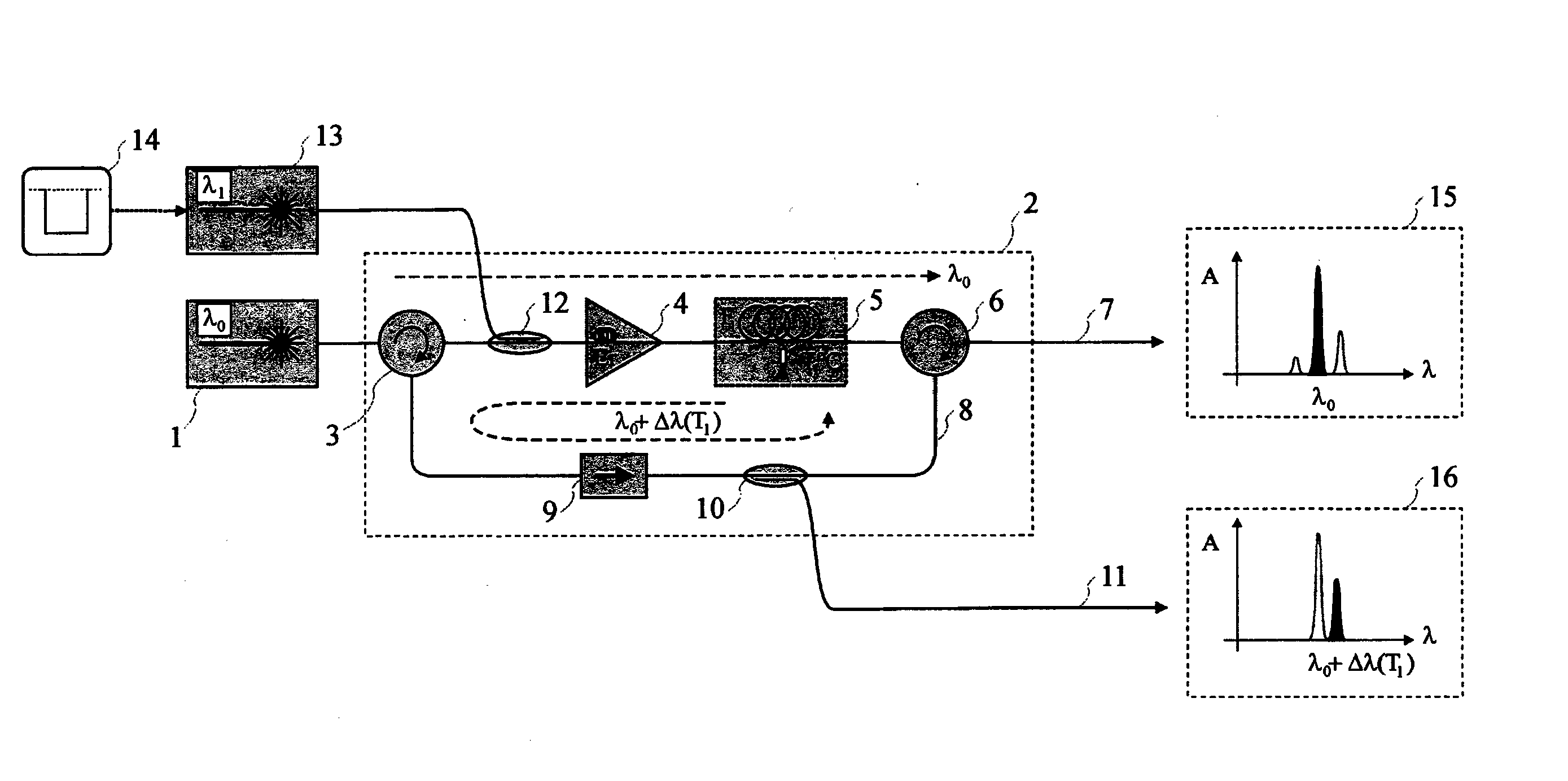
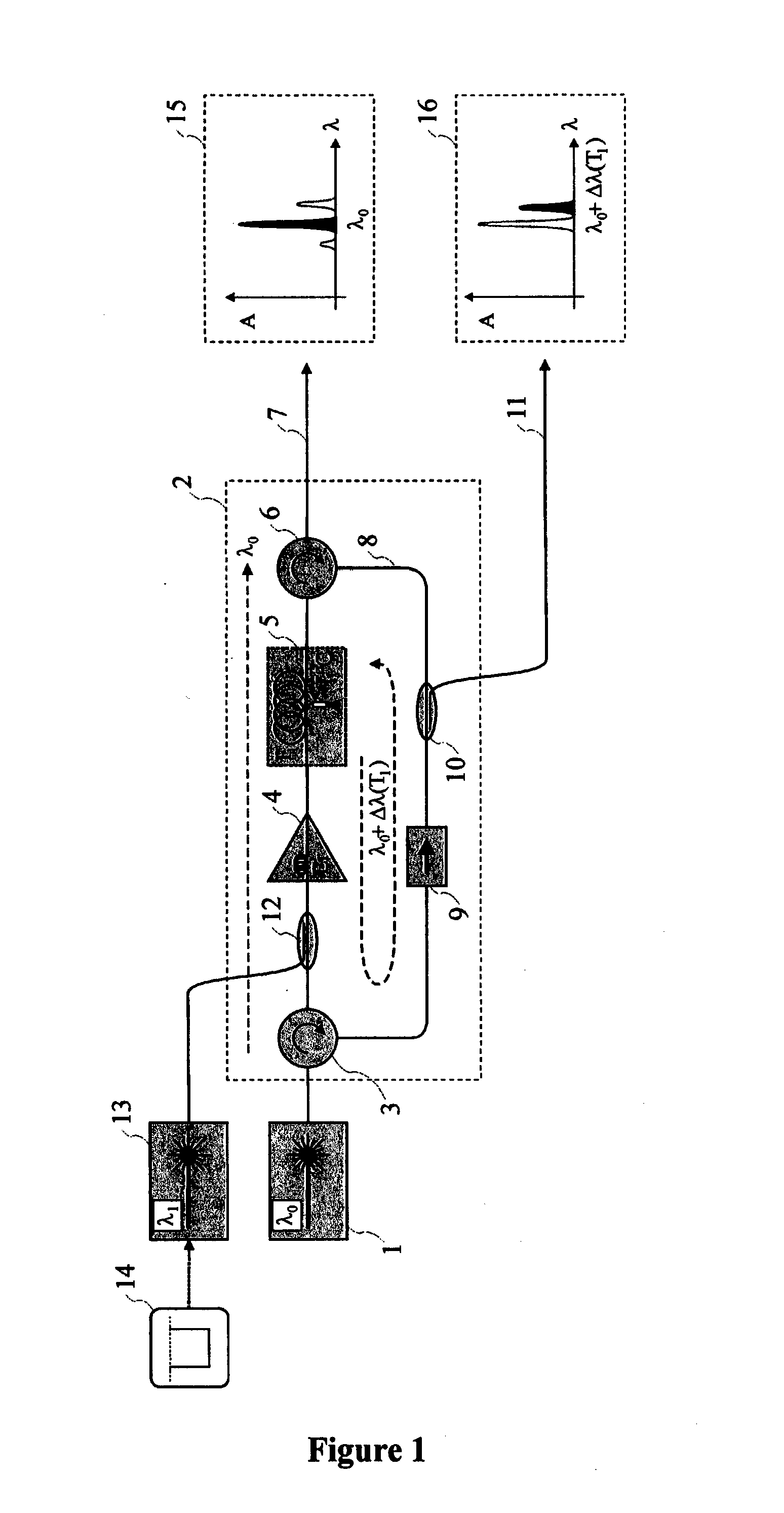
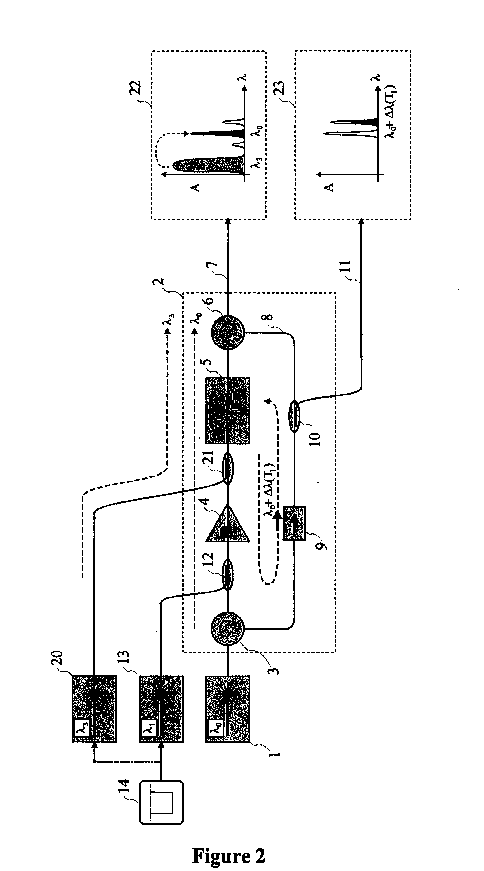
The present invention provides an apparatus for interrogating optical fibre sensors based on stimulated Brillouin scattering that overcomes the performance limitations and reduces the cost of existing devices. The system uses a cheap and efficient way to produce the "stimulus" or "probe" radiation, and the wavelength of the "probe" radiation is known and controllable with accuracy. Additionally, the invention provides an apparatus where the radiation produced inside the ring-type Brillouin resonator is intrinsically locked to the wavelength of the primary LASER source with a wavelength shift that can be accurately controlled by controlling the temperature and / or strain conditions of at least one part of the ring-type optical circuit. Furthermore, the invention provides an apparatus comprising one purging system for the ring-type Brillouin resonator capable to quench the distortion of the spectrum of the radiation produced by the same resonator in example consequent with a change of the tuning of the wavelength shift.

Problems solved by technology

In the document WO9827406A1 the spectrum of Brillouin photons is analysed with a tuneable optical filter having bandwidth narrow enough, a part that in the practice is very fragile, big and very expensive.
The practical implementation of such solutions requires electro-optical detectors balanced and with very wide band that are very expensive.
Implementing such systems requires very expensive balanced electro-optical detectors since the efficiency of spontaneous Brillouin effect is scarce.
Implementing the known solutions requires to use optical intensity modulators having very wide bandwidth and / or couples of sources of light radiation frequency locked the one with the other, parts that are delicate and are characterized by a very high cost.
Known Brillouin ring LASERS are characterized by limitations in the spectral purity of the resonance radiation, limitations that are substantially due to the bandwidth characteristic for the stimulated Brillouin emission that is at the origin of their operation.
Said limitations make the known Brillouin ring LASER devices non perfectly suited to be used in applications where the radiation that they produce is used for a detailed study of the Brillouin scattering spectrum in other propagation media.
Known Brillouin ring LASER devices are besides characterized by technical limitations due to the continuous recirculation of the oscillation radiation, recirculation that during the phases of tuning of the of the oscillation wavelength keeps trace of the wavelengths previously tuned for a certain interval of time, thus causing a transitory alteration of the oscillation spectrum that quenches slowly during the time (tuning distortion).
The said solution, that is conceptually assimilable to that described in the document EP0887624A2, retains the performance limitations that characterize the solutions based on spontaneous scattering and remains characterized by the high manufacturing costs that characterize the heterodyne systems.
Are not known solutions comprising ring Brillouin LASERS to achieve systems based on the stimulated Brillouin scattering or that can breakthrough the performance limitations and cut the level of cost common to known devices.

Method used


Image

  • Apparatus for interrogating distributed stimulated brillouin scattering optical fibre sensors using a quickly tuneable brillouin ring laser
  • Apparatus for interrogating distributed stimulated brillouin scattering optical fibre sensors using a quickly tuneable brillouin ring laser
  • Apparatus for interrogating distributed stimulated brillouin scattering optical fibre sensors using a quickly tuneable brillouin ring laser

Examples


Embodiment Construction

[0048]Selected combinations of aspects of the disclosed technology correspond to a plurality of different embodiments of the present invention. It should be noted that each of the exemplary embodiments presented and discussed herein should not insinuate limitations of the present subject matter. Features or steps described as part of one embodiment may be used in combination with aspects of another embodiment to yield yet further embodiments.

[0049]Additionally, certain features may be interchanged with similar devices of features not expressly mentioned which perform the same or similar function.

[0050]The invention will now be illustrated referring to the attached figures that represent preferred embodiments of the same not binding with respect to the protection purposes of the present document.

[0051]FIG. 1 discloses a non-limiting partial schematic representation of a ring-type Brillouin resonator circuit according to the present invention that accepts an input optical radiation pr...


PUM


Abstract

Device for measuring the distribution of strain and / or temperature along an optical fibre through the analysis of the stimulated Brillouin scattering, characterized by the fact that both the “optical pump” light from which the scattered energy is derived, and the “stimulus” or “probe” light that stimulates the scattering process are both derived by the same ring-type tuneable optical circuit that at the same type amplifies the amplitude of the “optical pump” light and generates, through a controlled Brillouin amplified scattering, the “probe” light having the spectrum linewidth required for the measurement needs and a wavelength shift with respect to the “optical pump” light that is accurately and quickly tuneable and fully adjustable within the range that is needed for interrogating a distributed optical fibre sensor.

Description

TECHNICAL FIELD OF THE INVENTION[0001]The present invention concerns an apparatus intended to interrogate distributed optical fibre sensors by time-domain analysis of the changes of optical intensity induced by stimulated Brillouin scattering between optical “pump” light produced by a primary source and optical “probe” light produced from the primary source by means of a tuneable Brillouin ring-type circuit.BACKGROUND OF THE INVENTION[0002]The “Brillouin effect” is a non linear scattering phenomenon in which incident photons of light interact with mechanical vibrations of the medium inside which they propagates to get scattered with a wavelength shifted with respect to the original one, in which the wavelength shift is related to the electro-optical characteristics of the same medium and to the physical characteristics, among which mechanical strain and temperature, that can later such characteristics.[0003]Due to the small entity of the Brillouin wavelength shift in conventional op...

Claims


Application Information

Patent Timeline
IPC IPC(8): G01D5/353
CPCG01D5/35364
Inventor BASTIANINI, FILIPPO
Owner BASTIANINI FILIPPO
Learn More