
Heart valve prosthesis

Inactive Publication Date: 2016-01-07
SHANGHAI MICROPORT CARDIOFLOW MEDTECH CO LTD
View PDF6 Cites 3 Cited by
  • Summary
  • Abstract
  • Description
  • Claims
  • Application Information

AI Technical Summary

Benefits of technology

The present invention provides a heart valve prosthesis with a valve stent that can close adhesively to the valve annulus, preventing perivalvular leakage. Additionally, the stent can be easily and accurately placed, minimizing the possibility of displacement. The stent design prevents blockages in the left bundle branch and ensures blood flow to the coronary artery ostia. The stent has a concave contour that enables self-deployment and a wedge-shaped inflow section that prevents ostia obstruction. These features prevent serious complications and facilitate the implantation process.

Problems solved by technology

However, even in developed countries, there are still many patients with severe aortic valve disease who are inoperable due to a number of reasons such as late stages of the disease, advanced ages or multiple comorbidities.
Calcium may deposit around the aortic valve over time, which can narrow the aortic valve and / or make it close insufficiently, thus causing “aortic regurgitation”.
Because these symptoms can lead to a serious decline in the quality of life and a significantly shortened survival time, effective treatment is necessary.
However, those prosthetic aortic valves commercially available still have some insufficient or unreasonable features.
Inaccurate deployment of the prosthesis is very likely to cause a fatal complication such as coronary artery ostium obstruction or bundle branch block.
With regard to the above two representative valve systems (Edwards and CoreValve), their weakness lies in not allowing retrieve or relocation.
Once an Edwards valve stent has been rapidly expanded by balloon inflation and deployed to the desired position, further adjustments of the Edwards valve stent are impossible.
During the course of the deployment of a CoreValve valve stent, some degree of adjustment is allowed, however further adjustments of the CoreValve valve stent are impossible after completion of the deployment.
As a result, if deployment location deviates from target or implantation of improper size stent happens, the possible occurrence of stent displacement will cause serious complication, which might threaten the patient's life.
Further, in the clinical use, CoreValve valve stents are frequently reported to cause bundle branch damage due to excessive extension in the ventricle or displace from the deployment position after implantation.

Method used


Image

  • Heart valve prosthesis
  • Heart valve prosthesis
  • Heart valve prosthesis

Examples


Embodiment Construction

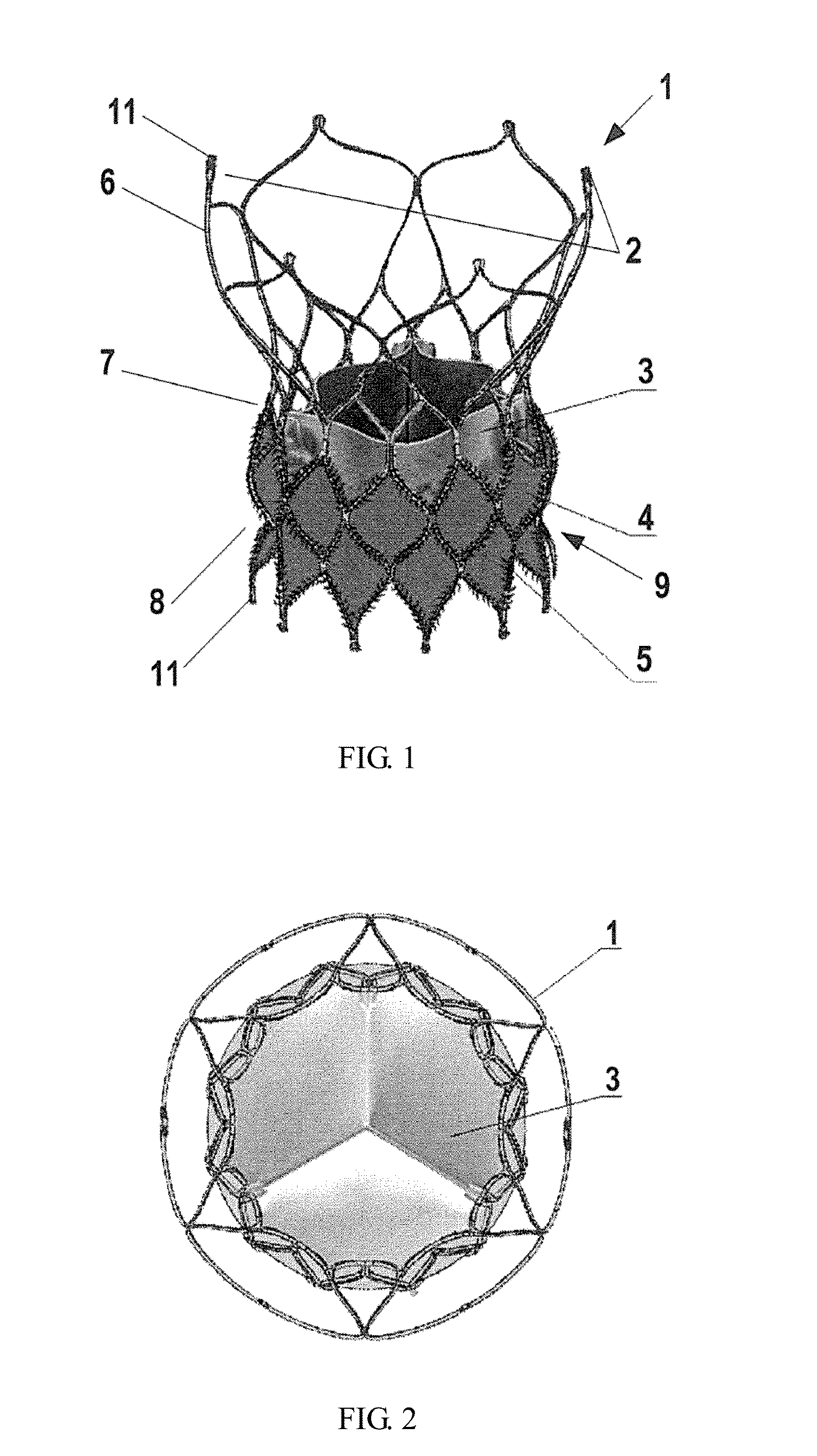
[0031]The present invention is described in greater detail below with reference to specific embodiments. In general terms, the invention relates to a heart valve prosthesis having a self-expanding stent for supporting a heart valve. Along a longitudinal axis of the self-expanding stent, it has a proximal portion, an intermediate portion and a distal portion. In the context of the present application, the proximal portion corresponds to an inflow portion of the prosthesis, and accordingly, the distal portion corresponds to an outflow portion thereof.

[0032]FIG. 1 shows an exemplary embodiment of the heart valve prosthesis according to the present invention. Specifically, the heart valve prosthesis may be an interventional aortic valve prosthesis for replacing a defective aortic valve. The valve prosthesis includes a stent 1 and a prosthetic aortic valve 3. The valve 3 is affixed to an internal surface of the stent 1, for example, by sewing. The stent 1 has a contracted configuration f...


PUM


Abstract

A stent (1) used for a heart valve prosthesis and the heart valve prosthesis that includes the stent (1) and is used for heart valve replacement. The stent is configured to support a heart valve (3) and includes, along a longitudinal axis, an inflow section (8), an outflow section (6) and a transition section (7) between the inflow section (8) and the outflow section (6). The stent (1) has a contracted delivery configuration and an expanded deployed configuration. In the expanded deployed configuration, the inflow section (8) defines a concave contour that is complementary to a structure of a native valve annulus. The concave contour enables self-deployment and close adherence of the stent (1), thereby preventing its displacement and perivalvular leakage after implantation.

Description

TECHNICAL FIELD[0001]This invention relates generally to heart valve prosthesis for use in minimally invasive heart valve replacement. In particular, the invention relates to a stent for use with a heart valve prosthesis, which can be deployed with close adherence to the anatomical structure of the heart and with minimal possibility of displacement and perivalvular leakage.BACKGROUND[0002]With the aging of the global population, aortic valve disease has become one of the most common cardiovascular diseases, with an incidence of 2%-5% in China and ranking as the third most frequent disease after coronary heart disease and hypertension in the West. Every year, tens of thousands of patients benefit from the surgical aortic valve replacement (SAVR). However, even in developed countries, there are still many patients with severe aortic valve disease who are inoperable due to a number of reasons such as late stages of the disease, advanced ages or multiple comorbidities. The debut of perc...

Claims


Application Information

Patent Timeline
IPC IPC(8): A61F2/24
CPCA61F2/2418A61F2/2412A61F2230/0067A61F2220/0075A61F2210/0014A61F2230/0078A61F2230/008A61F2250/0036
Inventor CHEN, GUOMINGLI, YUHUANG, FENGHUANG, LEIHAN, JIANCHAODUAN, YIHAOCHEN, SHAOHUILUO, QIYI
Owner SHANGHAI MICROPORT CARDIOFLOW MEDTECH CO LTD
Features
  • Generate Ideas
  • Intellectual Property
  • Life Sciences
  • Materials
  • Tech Scout
  • Unparalleled Data Quality
  • Higher Quality Content
  • 60% Fewer Hallucinations
Learn More