Method for measuring a physical parameter and electronic circuit for implementing the same

a physical parameter and electronic circuit technology, applied in the direction of acceleration measurement in multiple dimensions, acceleration measurement using interia forces, instruments, etc., can solve the problem of reducing the sensitivity or gain of the electronic circuit, inevitably erroneous final value at the end of all the measurement cycles, and variation in the measured actual force. , to achieve the effect of rapid acquisition of at least one measurement signal

Active Publication Date: 2016-01-07
EM MICROELECTRONIC-MARIN
View PDF6 Cites 24 Cited by
  • Summary
  • Abstract
  • Description
  • Claims
  • Application Information

AI Technical Summary

Benefits of technology

[0013]It is thus an object of the invention to overcome the aforementioned drawbacks of the prior art by providing a method for measuring a physical parameter by means of an electronic circuit, which can rapidly provide at least one digital measurement signal while removing the effects of stray capacitances.
[0024]Advantageously, performing successive measurement cycles with positive and negative polarizations on the resistive sensor makes it possible to remove the offsets related to the MEMS sensor and to the electronic interface connected to the sensor, and the low frequency noise.
[0026]Advantageously for the measurement method, there is great flexibility of operation of the algorithm implemented in the logic unit. This type of smart algorithm makes it possible to have a large oversampling ratio, as a result of small adaptation steps of each digital measurement signal for the converter, and high responsiveness, as a result of large adaptation steps of each digital measurement signal for the converter.
[0027]To achieve this, the measurement method advantageously uses a self-adaptive algorithm to detect large changes in the physical parameter, particularly between two successive conversions or within the same conversion. After a certain number of measurement cycles in small steps, a decision counter determines whether a continual increase or a continual decrease occurs in the digital signals, in order to adapt the size of each step of the subsequent measurement cycles. Adaptation of each step to a large digital value occurs as soon as a predetermined counting threshold of a decision counter is exceeded. As soon as the decision counter determines a change of sign in the measurement cycles with a large step value, the step size of each measurement cycle is re-adapted to small steps to reduce noise.
[0032]One advantage of the electronic interface circuit of a physical sensor lies in the fact that it makes it possible to rapidly obtain at least one measurement signal at the logic unit output, since the resistive sensor is successively polarized in a positive polarization followed by a negative polarization. The logic unit is capable of implementing a stored self-adaptive algorithm to adapt the size of the adaptation steps of the measurement cycles to provide digital signals adapted as a result of detection of a large change in the physical parameter measured during a measurement conversion. Two digital signals depending on a positive polarization or first polarization, and on a negative polarization or second polarization of the fixed electrodes of the pair of capacitors are generally provided in the logic unit. By combining the digital signals this enables any voltage offset to be removed from the electronic circuit components.

Problems solved by technology

Thus, stray capacitances are added to the capacitances of the capacitors of the MEMS capacitive sensor, which creates non-linearities and also reduces the sensitivity or gain of the electronic circuit.
The stray capacitances of the MEMS capacitive sensor together with those of the electronic interface result in a variation in the measured actual force, which is a drawback.
If an error occurs during the first measurement with a large change step in the logic unit, the final value at the end of all the measurement cycles will inevitably be erroneous, which constitutes a drawback.
This slows down the supply of digital measurement signals at the end of each conversion, which constitutes another drawback.
Measurement is relatively complicated with this measurement device and does not concern an acceleration measurement.
However, no information is mentioned as to how to perform a measurement with the accelerometer.

Method used


Image

  • Method for measuring a physical parameter and electronic circuit for implementing the same
  • Method for measuring a physical parameter and electronic circuit for implementing the same

Examples


first embodiment

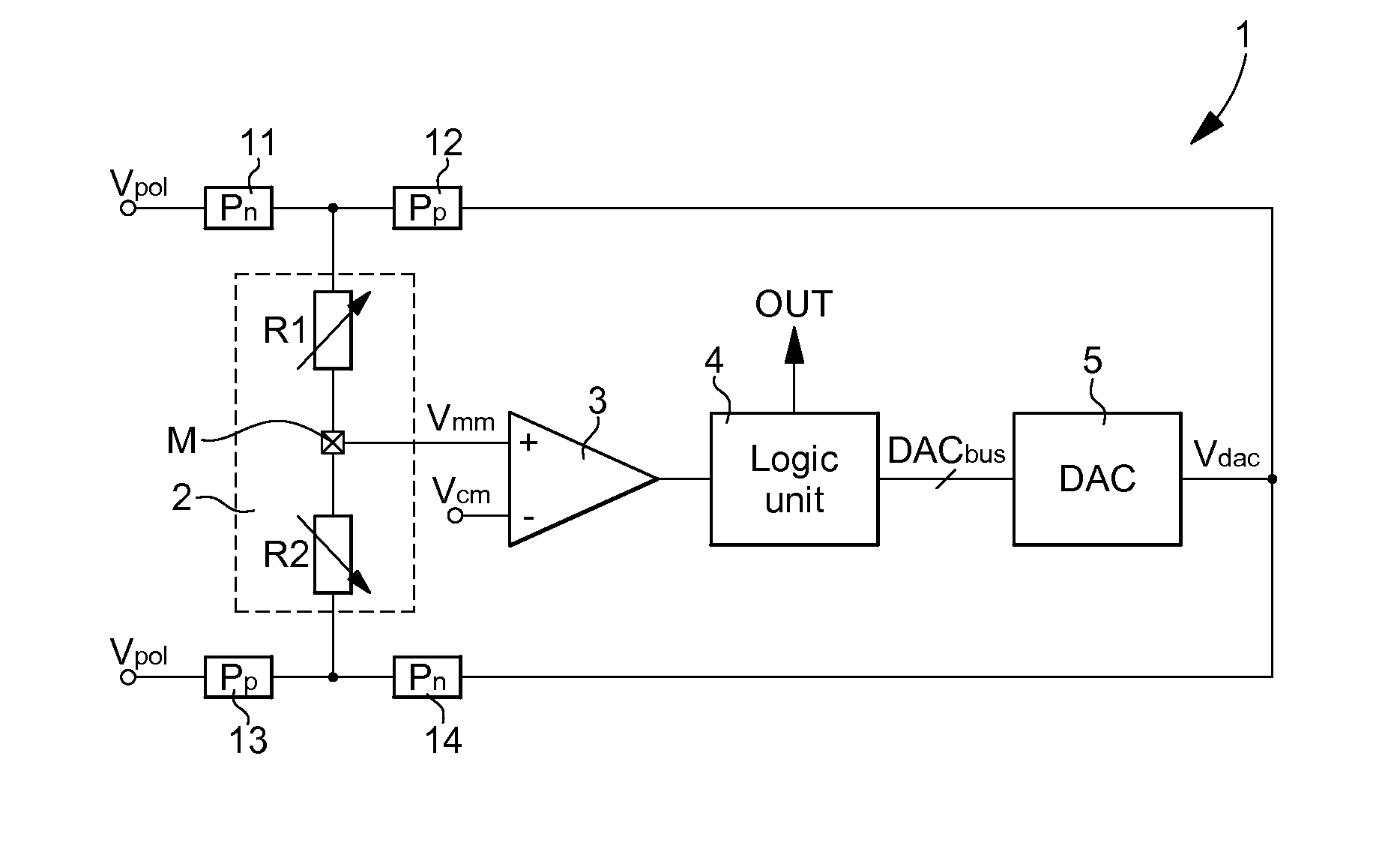
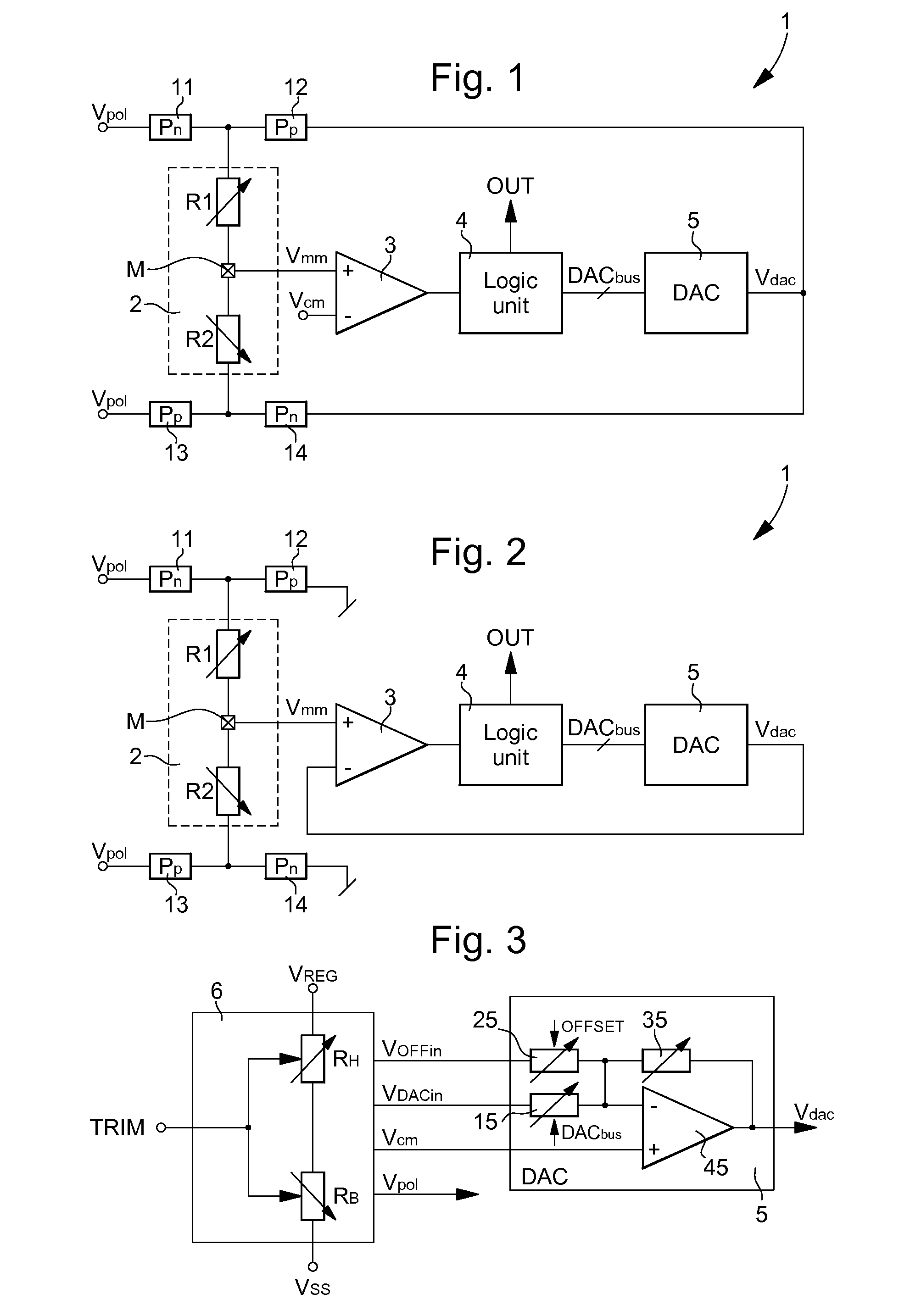
[0038]FIG. 1 shows a simplified diagram of the electronic resistive sensor circuit 2 for a physical parameter measurement, such as an acceleration or an angular velocity, or even a pressure or a force in at least one direction. Resistive sensor 2 is composed of a resistive divider with two resistors R1 and R2 which are series connected. As explained below, each resistor R1 and R2 is a strain gauge whose resistance value varies according to the motion of a moving mass M in a fixed structure of the resistive MEMS sensor. Moving mass M is disposed at the connection node of resistors R1, R2, and moves as a function of the acceleration or of the angular velocity to be measured.

[0039]A connection node of resistors R1, R2 is connected to a first input of an amplifier-comparator 3, which forms part of an electronic interface connected to resistive MEMS sensor 2. The first input of the amplifier-comparator is preferably the positive input, whereas a second input, which is preferably the nega...

second embodiment

[0069]There is provided for this second embodiment a resistive sensor 2 with a single resistive divider for a measurement on one axis. However, as previously described, it is possible to envisage having a resistive sensor 2 with three resistive dividers for a measurement on three axes.

[0070]The main difference of this second embodiment is that the output voltage of digital-to-analogue converter 5 Vdac is provided directly to the second input of amplifier-comparator 3, which is preferably the negative input. The first input of amplifier-comparator 3 remains connected to moving mass M and to the connection node of the two resistors R1 and R2 of the resistive divider.

[0071]The switching unit still includes the four switches 11, 12, 13, 14 which may be formed of conventional MOS transistors each controlled across the gate by a respective control signal. The first switch 11 is disposed between a polarization voltage source Vpol and a free end of first resistor R1. The second switch 12 is...


PUM


Abstract

The physical parameter measurement method is performed using an electronic circuit (1) with a resistive sensor (2). The resistive sensor includes two resistors (R1, R2) mounted in series, whose connection node connected to a moving mass (M), is connected to a first input of an amplifier-comparator (3). A second input of the amplifier-comparator receives a reference voltage. One output of the amplifier-comparator is connected to a logic unit (4), which provides a digital output signal (OUT). A digital-to-analogue converter (5) provides a measurement voltage (Vdac), as a function of a digital signal provided by the logic unit, to the first resistor (R1) in a first phase of a measurement cycle, whereas the second resistor (R2) is polarized by a polarization voltage, and to the second resistor in a second phase, whereas the first resistor is polarized by a polarization voltage via a switching unit.

Description

[0001]This application claims priority from European Patent Application No. EP14175967.0 filed Jul. 7, 2014, the entire disclosure of which is hereby incorporated herein by reference.FIELD OF THE INVENTION[0002]The invention concerns a method for measuring a physical parameter, such as an acceleration or an angular velocity or a pressure or a force.[0003]The invention also concerns an electronic circuit for implementation of this physical parameter measurement method.BACKGROUND OF THE INVENTION[0004]Conventionally, for measurement of a physical parameter, such as an acceleration or an angular velocity, the electronic circuit includes a capacitive sensor connected to an electronic interface capable of outputting at least one measurement signal. The capacitive sensor is formed of two differential mounted capacitors whose common electrode is movable and forms part of an armature elastically retained between the two fixed electrodes.[0005]With this differential capacitive sensor, it is ...

Claims


Application Information

Patent Timeline
Patent Type & Authority Applications(United States)
IPC IPC(8): G01R27/02
CPCG01R27/02G01P15/12G01P15/18G01C19/5776G01L1/22G01D5/16
Inventor DESCHILDRE, ALEXANDREGROSJEAN, SYLVAIN
Owner EM MICROELECTRONIC-MARIN
Why Eureka
Try Eureka