DEVICES AND METHODS FOR CONTROLLlNG MAGNETIC ANISTROPY WITH LOCALIZED BIAXIAL STRAIN IN A PIEZOELECTRIC SUBSTRATE

a piezoelectric substrate and localized biaxial strain technology, applied in piezoelectric/electrostrictive/magnetostrictive devices, digital storage, instruments, etc., can solve problems such as film strain modifying the magnetic properties of materials

Active Publication Date: 2016-01-07
RGT UNIV OF CALIFORNIA
View PDF4 Cites 9 Cited by
  • Summary
  • Abstract
  • Description
  • Claims
  • Application Information

AI Technical Summary

Benefits of technology

[0014]The present technology exploits the edge effect that occurs at the edge of any surface electrode and dies off with distance from the electrode edge both toward and away from the electrode through the piezoelectric film. This is a highly in-plane strained region. Placing a magnetostrictive material on the surface of the film in this region results in the film strain modifying the magnetic properties of the material. This can lead to a number of devices and device configurations including square patterned electrodes separated by a distance on two or three thicknesses, the area under a square electrode with dimensions of the piezoelectric film thickness, the area along the edge of a line electrode, the area under a line electrode with width on the order of the piezoelectric film thickness, etc. Any magnetic feature can be placed in these in-plane strained regions to create a magnetoelectric effect.
[0015]Examples of devices include four and six patterned electrodes, memory devices, controlled permeability devices (switching from superparamagnetic to single domain ferromagnetic behavior), and any other device fabricated on thin film piezoelectric materials grown or deposited on a substrate wherein the electrode edge effects are taken advantage of to overcome the substrate clamping effect.

Problems solved by technology

Placing a magnetostrictive material on the surface of the film in this region results in the film strain modifying the magnetic properties of the material.

Method used


Image

  • DEVICES AND METHODS FOR CONTROLLlNG MAGNETIC ANISTROPY WITH LOCALIZED BIAXIAL STRAIN IN A PIEZOELECTRIC SUBSTRATE
  • DEVICES AND METHODS FOR CONTROLLlNG MAGNETIC ANISTROPY WITH LOCALIZED BIAXIAL STRAIN IN A PIEZOELECTRIC SUBSTRATE
  • DEVICES AND METHODS FOR CONTROLLlNG MAGNETIC ANISTROPY WITH LOCALIZED BIAXIAL STRAIN IN A PIEZOELECTRIC SUBSTRATE

Examples


example 1

[0055]To further demonstrate the operational principles of the devices and methods, finite element simulations (FEA) were used to design nanoarchitectured devices that were fabricated and used to demonstrate highly localized voltage controlled manipulation of an engineered magnetic domain structure in a Ni ring. The layer thicknesses of the figures do not reflect scale. A schematic diagram of a device structure that can create magnetoelastic anisotropy on magnetic elements (a ring is shown as an example) in three directions by applying voltage on three pairs of electrodes is shown in FIG. 4A and sequential actuation of the paired electrodes is shown in FIG. 4B through FIG. 4D.

[0056]The structure consists of a Si wafer substrate 68, a bottom electrode 66, a PZT thin film 64, and, in this case, three pairs of electrodes surrounding a middle magnetic element. The electrode 70 is paired with electrode 72 and is designated (A-A). Electrode 74 is paired with electrode 76 (B-B) and electro...

example 2

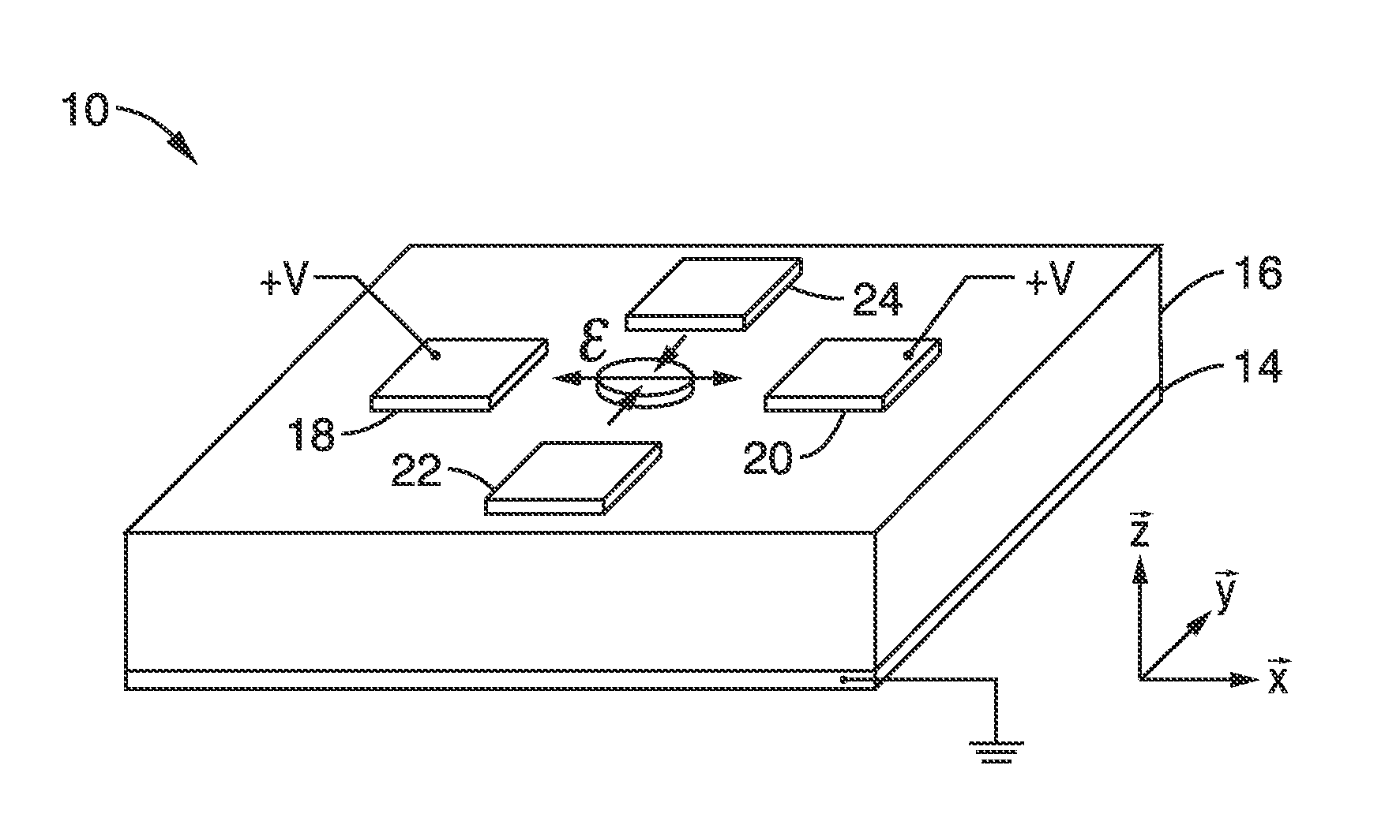
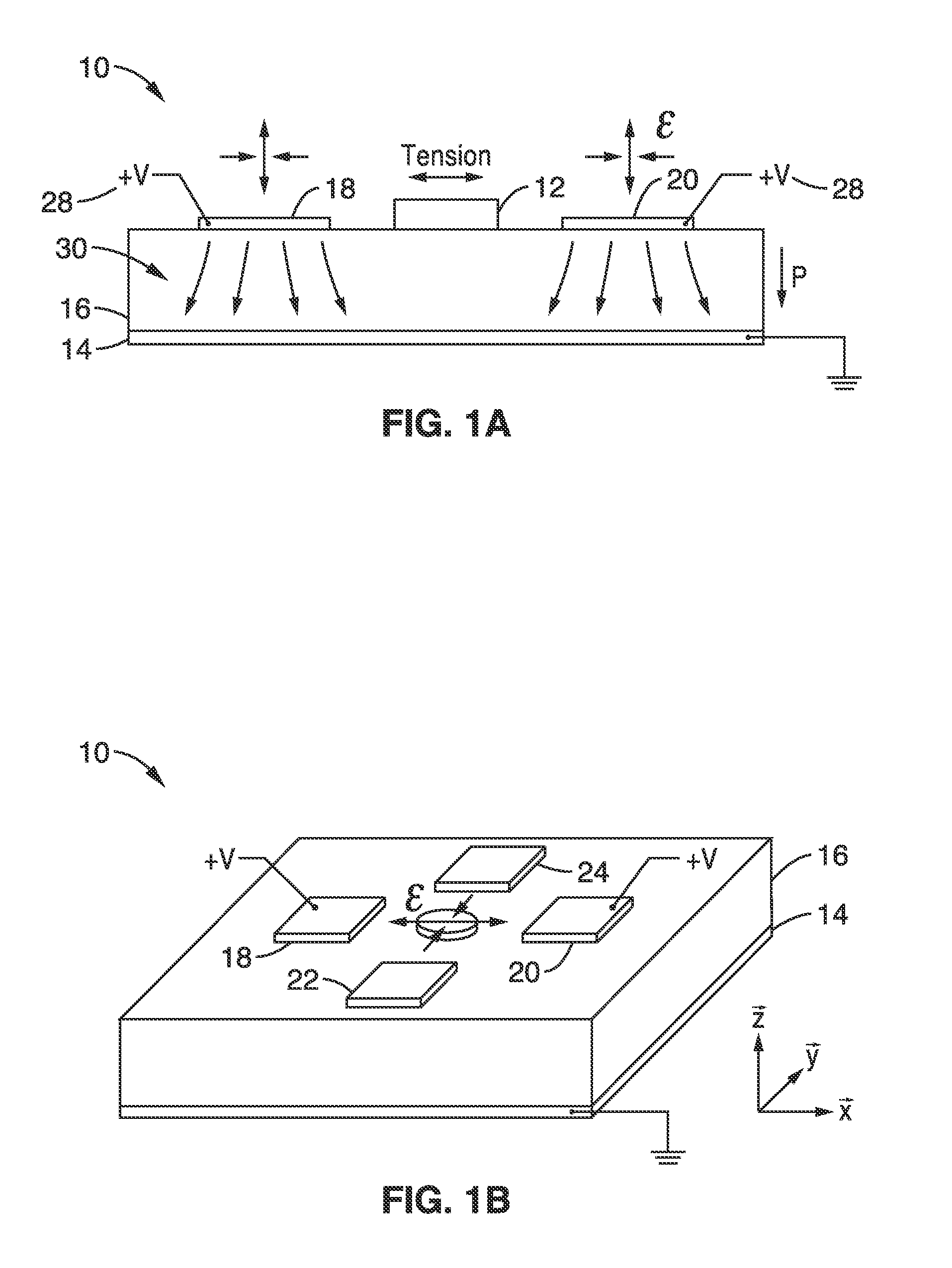
[0065]In order to demonstrate the technology, an analytical model of a device with the structure shown in FIG. 1A and FIG. 1B was constructed to demonstrate the reorientation of the magnetization of a magnetostrictive ellipse, a configuration that could represent a memory bit or a component of a memory bit that could be part of an array of bits. The memory bit included an elliptical ferromagnetic element deposited on a ferroelectric layer with four patterned electrodes around the ferromagnetic element. All four boundaries of the PZT thin film were clamped by a Si substrate.

[0066]Specifically, the structure had a 500 nm piezoelectric transducer (PZT)-5H thin film with a Pt bottom ground electrode deposited onto a 0.5 mm thick Si substrate. A 150 nm×120 nm×10 nm Ni ellipse was surrounded by four 125 nm×125 nm×10 nm Au electrodes in this example. The two electrodes A-A were at a 45° angle, and the two electrodes B-B were at a 135° angle relative to the major axis of the ellipse (i.e., ...


PUM


Abstract

Devices and methods for controlling magnetic anisotropy and orientation of magnetic single domain structures between stable states are provided based on piezoelectric thin films and patterned electrodes. By using patterned electrodes, piezoelectric strain is manipulated to achieve a highly localized biaxial strain in a piezoelectric substrate and rotate the magnetic anisotropy of magnetic materials. Reorientation of a magnetic single domain between different stable states is accomplished by pulsing voltage across pairs of electrodes. Since only a small region surrounding the electrodes is strained, the methods can be applied to arrays of indexed magnetic elements and to piezoelectric thin films clamped to silicon base substrates.

Description

CROSS-REFERENCE TO RELATED APPLICATIONS[0001]This application claims priority to, and the benefit of, U.S. provisional patent application Ser. No. 62 / 011,679 filed on Jun. 13, 2014, incorporated herein by reference in its entirety.STATEMENT REGARDING FEDERALLY SPONSORED RESEARCH OR DEVELOPMENT[0002]This invention was made with Government support under 1160504, awarded by the National Science Foundation. The Government has certain rights in the invention.INCORPORATION-BY-REFERENCE OF COMPUTER PROGRAM APPENDIX[0003]Not ApplicableBACKGROUND[0004]1. Technical Field[0005]The present technology pertains generally to magnetoelectric heterostructures and more particularly to devices and methods that manipulate magnetic anisotropy of magnetic materials using highly localized biaxial strain in a piezoelectric substrate with patterned electrodes. Since only a small region surrounding the electrodes is strained, arrays of indexed magnetic elements can be created.[0006]2. Background[0007]The man...

Claims


Application Information

Patent Timeline
Patent Type & Authority Applications(United States)
IPC IPC(8): H01L41/047G11C11/14G11C11/16H01L41/053H01L41/09
CPCH01L41/0472G11C11/14H01L41/09G11C11/1673H01L41/053G11C11/161G11C11/1675G11C2013/0095H10N30/00H10N30/87H10N30/204
Inventor LYNCH, CHRISTOPHER S.CUI, JIZHAIHOCKEL, JOSHUACARMAN, GREGORY P.
Owner RGT UNIV OF CALIFORNIA
Why Eureka
Try Eureka