Cutting blasting method based on pre-blasting
A technology of pre-blasting and cutting holes, which is applied in blasting and other directions, can solve the problems of low utilization rate of blast holes, poor cutting effect, and large blasting supply that cannot be cut, so as to overcome the effect of surrounding rock sandwiching and improve The effect of the gouging effect
- Summary
- Abstract
- Description
- Claims
- Application Information
AI Technical Summary
Problems solved by technology
Method used
Image
Examples
Embodiment 1
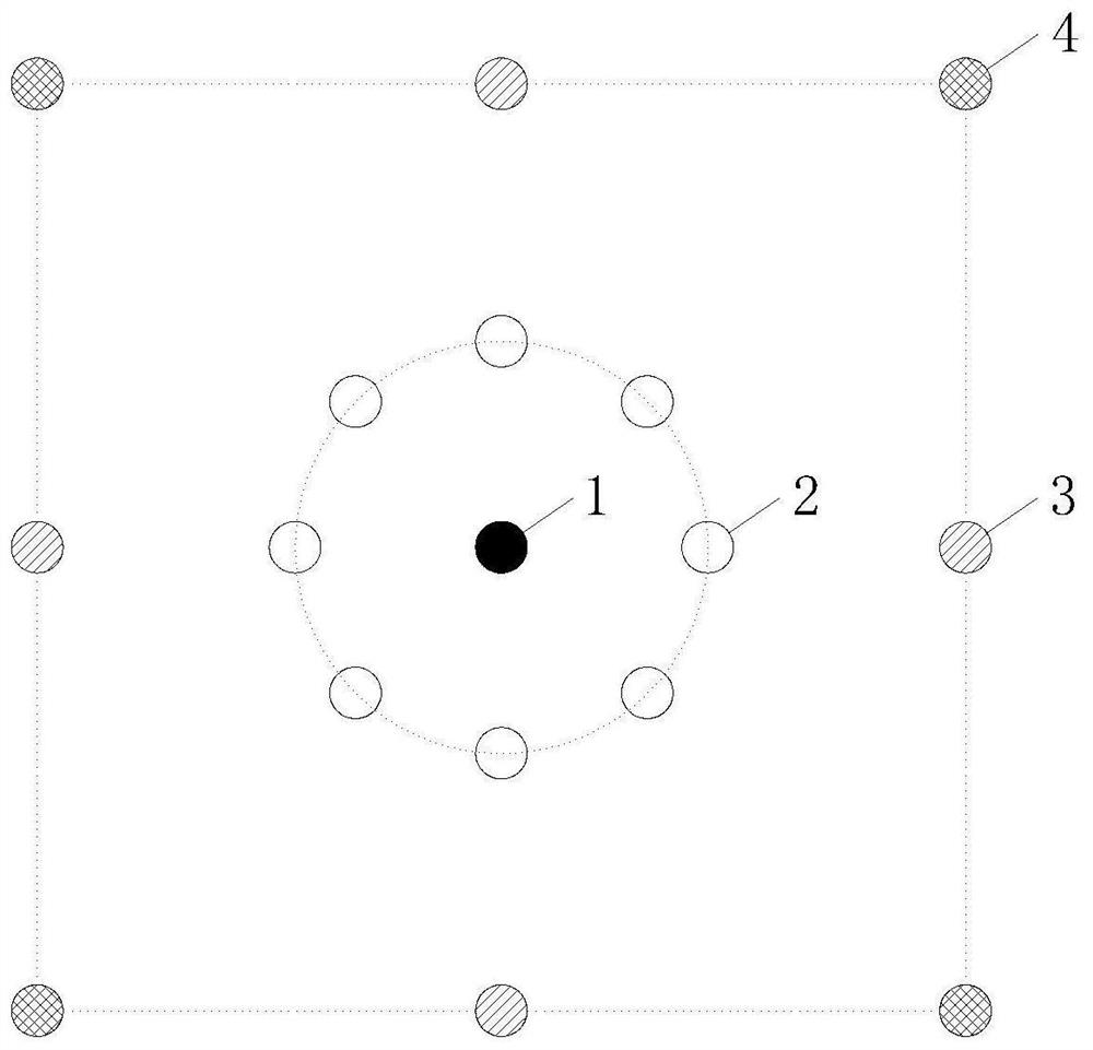
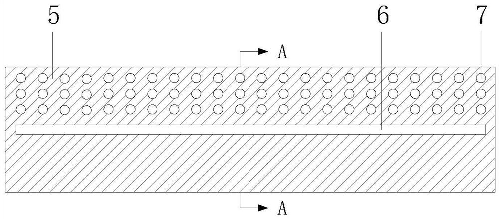
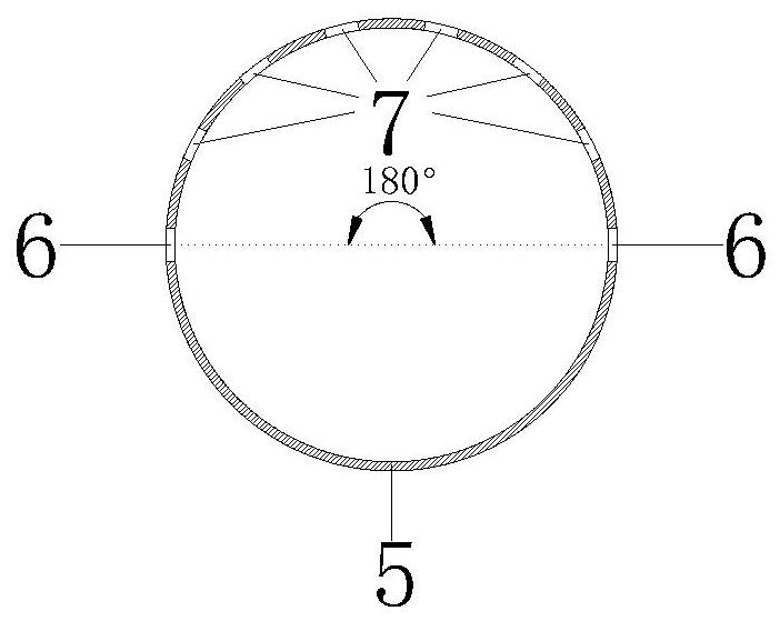
[0039] In this embodiment, the cutting blasting method based on pre-blasting is adopted for a section of a roadway without gas and coal dust explosion hazards, such as Figure 1-5 As shown, the specific operation steps are as follows:
[0040] 1) Drill a central charging hole 1 in the center of the cutting area, drill a circle of empty holes 2 around the central charging hole 1, drill four main cutting holes 3 and four compensation cutting holes around the empty hole 2 4. The four compensation cut holes 4 are arranged in a square shape, the four main cut holes 3 are all located in the center of the line connecting the adjacent compensation cut holes 4, and auxiliary holes, caving holes and peripheral holes are sequentially drilled outside the cut holes;
[0041] Among them, based on the lithology and drilling equipment, the depth of the central charging hole 1, the main cutting hole 3 and the compensation cutting hole 4 is designed to be 2400mm, the depth of the empty hole 2 i...
Embodiment 2
[0051] This embodiment also adopts the cutting blasting method based on pre-blasting for a roadway without gas and coal dust explosion hazard. 0.6 times of the radius of the crack circle of charge hole 1, bring relevant parameters into The radius of the crack circle of the center charging hole 1 is 347mm, and the radius of the circle where the empty hole 2 is located is equal to 208mm. To facilitate the drilling operation, the radius of the circle where the empty hole 2 is located is 210mm, and the diameter of the circle where the empty hole 2 is located is 420mm. ;
[0052] Among them, the side length of the square where the main cut hole 3 and the compensation cut hole 4 are designed is twice the diameter of the circle where the empty hole 2 is located, which is equal to 840mm after calculation;
[0053] Among them, the distance between the designed empty holes 2 is 4 times the diameter of the empty holes 2, which is equal to 168 mm after calculation. To facilitate the dri...
Embodiment 3
[0056] This embodiment also adopts the cutting blasting method based on pre-blasting for a tunnel without gas and coal dust explosion hazard. 0.6 times of the radius of the crack circle of charge hole 1, bring relevant parameters into The radius of the crack circle of the center charging hole 1 is 347mm, and the radius of the circle where the empty hole 2 is located is equal to 208mm. To facilitate the drilling operation, the radius of the circle where the empty hole 2 is located is 210mm, and the diameter of the circle where the empty hole 2 is located is 420mm. ;
[0057] Among them, the side length of the square where the main cut hole 3 and the compensation cut hole 4 are designed is twice the diameter of the circle where the empty hole 2 is located, which is equal to 840mm after calculation;
[0058] Among them, the distance between the designed empty holes 2 is 4 times the diameter of the empty holes 2, which is equal to 168 mm after calculation. To facilitate the dril...
PUM
 Abstract
Description
Claims
Application Information
 - R&D
- Intellectual Property
- Life Sciences
- Materials
- Tech Scout
- Unparalleled Data Quality
- Higher Quality Content
- 60% Fewer Hallucinations
Browse by: Latest US Patents, China's latest patents, Technical Efficacy Thesaurus, Application Domain, Technology Topic, Popular Technical Reports.
© 2025 PatSnap. All rights reserved.Legal|Privacy policy|Modern Slavery Act Transparency Statement|Sitemap|About US| Contact US: help@patsnap.com


