Antenna device and array antenna device

a technology of array antenna and antenna, which is applied in the direction of stripline fed array, polarised antenna unit combination, waveguide horn, etc., can solve the problems of increasing the manufacturing cost and manufacturing process, the power feeding structure is complicated, and the antenna is mounted on a mobile body such as a vehicle or an airplane. , to achieve the effect of satisfactory radiation pattern, small size and improved reflection characteristi

Active Publication Date: 2016-01-07
MITSUBISHI ELECTRIC CORP
View PDF3 Cites 9 Cited by
  • Summary
  • Abstract
  • Description
  • Claims
  • Application Information

AI Technical Summary

Benefits of technology

[0053]According to the present invention, since the antenna device includes, above the first excitation circuit, the first matching element composed of the conductor, it is possible to improve a reflection characteristic even if the cavity is reduced in size, and therefore, there is an advantageous effect that it is possible to obtain an antenna device that is usable in a wide band and can be configured in a small size.
[0054]In addition, when a plurality of the

Problems solved by technology

In satellite communication or the like, a loading space and/or a loading weight of an antenna mounted on a mobile body such as a vehicle or an airplane are limited.
Though an antenna described in Patent Document 1 mentioned below is adapted to orthogonal polarization, a patch antenna is used, and even when a non-exciting element that contributes to a wider band is added thereto, in general, the band is approximately 10%, and therefore, there is a problem such that a wider band more than the above is difficult.
However, when a plurality of the antennas are disposed as element antennas to conf

Method used


Image

  • Antenna device and array antenna device
  • Antenna device and array antenna device
  • Antenna device and array antenna device

Examples


first embodiment

[0077]An antenna device according to a first embodiment of the present invention is explained.

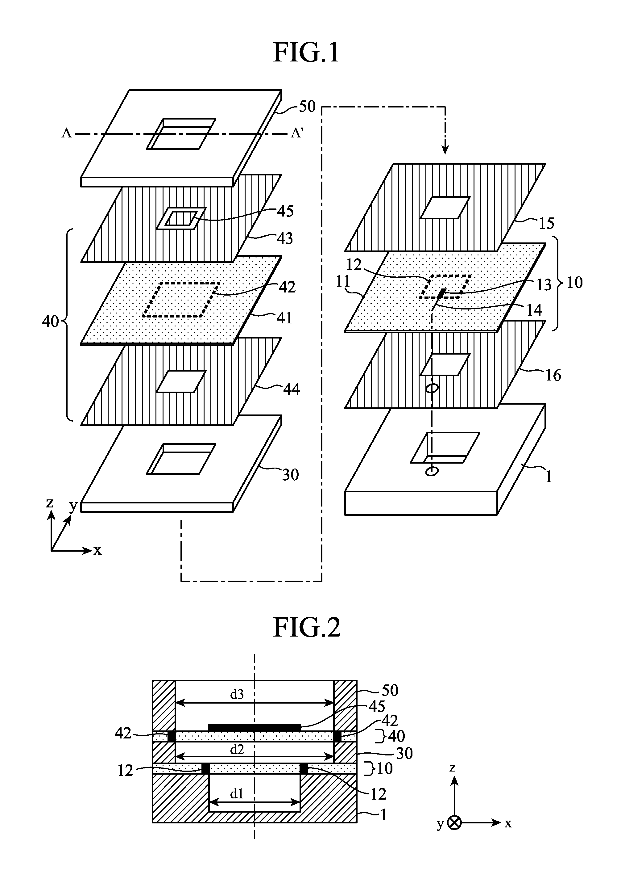
[0078]FIG. 1 is an exploded perspective view showing a configuration of an antenna according to the first embodiment of the present invention.

[0079]Note that, in order to simply show the configuration of the present invention, the first embodiment is assumed to be single polarization.

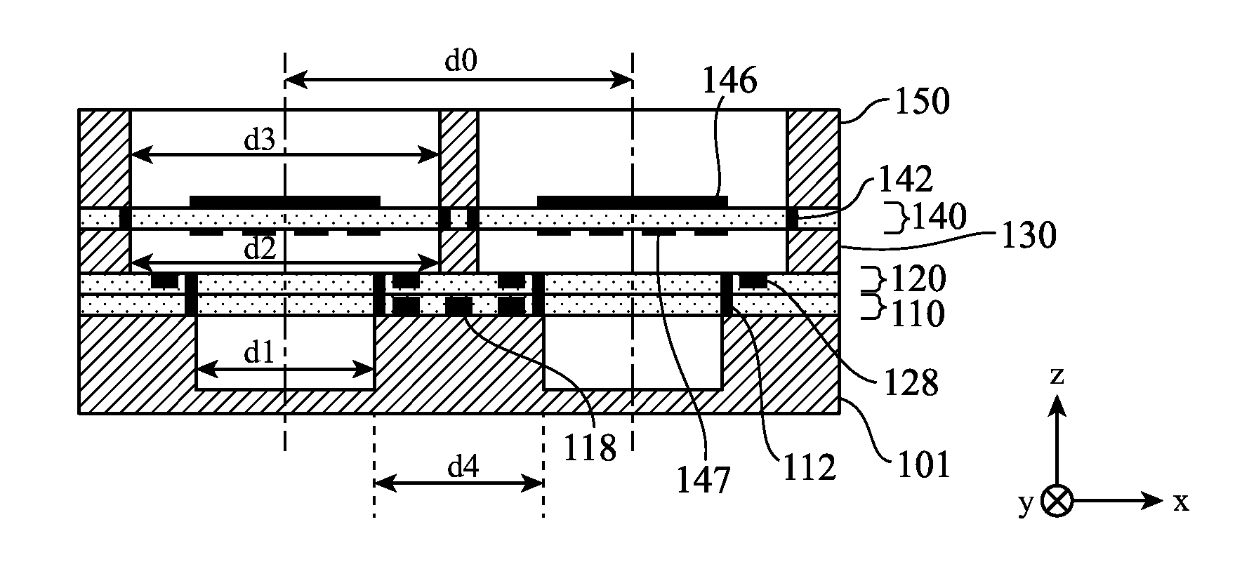
[0080]The antenna is composed of a first cavity part 1 closed in the bottom, a first excitation circuit 10 that excites a first polarized wave, a second cavity part (a radiation part) 30 having an open hole, a matching element section 40, and a third cavity part (a radiation part) 50 having an open hole.

[0081]The first cavity part 1 is composed of, for example, a metal in which an opening is cut.

[0082]Note that the bottom is closed.

[0083]The first excitation circuit 10 includes in a dielectric substrate 11 a first power feeding probe 13, and a first transmission line 14 that supplies a signal to the first power...

second embodiment

[0109]An antenna device according to a second embodiment of the present invention is explained.

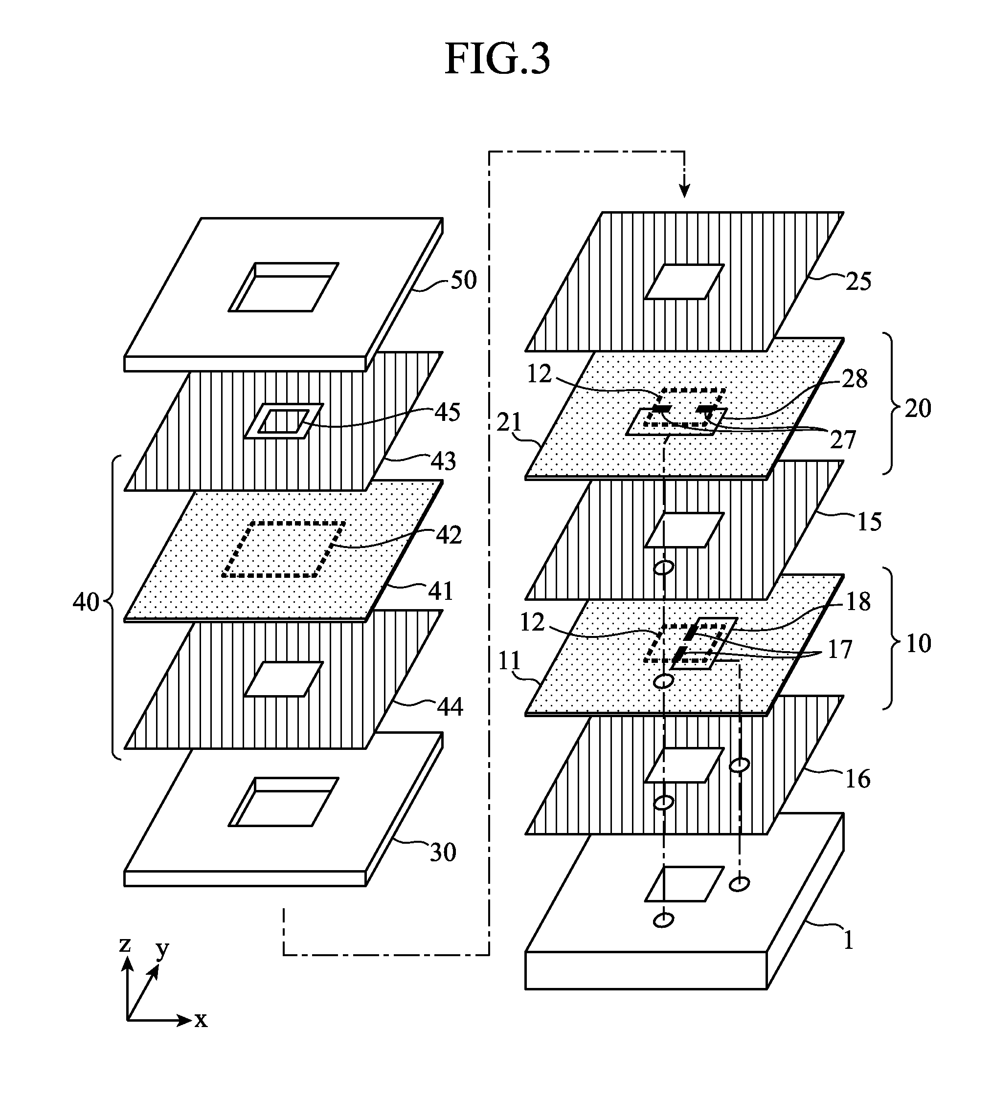
[0110]FIG. 3 is an exploded perspective view showing a configuration of an antenna according to the second embodiment of the present invention.

[0111]Note that, in order to simply show the configuration of the present invention, the second embodiment is assumed to be orthogonal double polarization.

[0112]In the figure, the second embodiment is the same as the first embodiment in that the antenna includes a first cavity part 1 closed in the bottom, a first excitation circuit 10 that excites a first polarized wave, a second cavity part 30 having an open hole, a matching element section 40, and a third cavity part 50 having an open hole.

[0113]Compared with the first embodiment, the second embodiment is different in the internal structure of the first excitation circuit 10, and different in that a second excitation circuit 20, a radiated polarized wave of which is orthogonal to a radiated polari...

third embodiment

[0132]An antenna device according to a third embodiment of the present invention is explained.

[0133]FIG. 4 is an exploded perspective view showing a configuration of an antenna according to the third embodiment of the present invention.

[0134]Note that, in order to simply show the configuration of the present invention, the third embodiment is assumed to be orthogonal double polarization.

[0135]In the figure, the third embodiment is the same as the second embodiment in that the antenna includes a first cavity part 1 closed in the bottom, a first excitation circuit 10 that excites a first polarized wave, a second excitation circuit 20 that excites a second polarized wave, a second cavity part (a lower radiation part) 30 having an open hole, a matching element section 40, and a third cavity part (an upper radiation part) 50 having the open hole.

[0136]Compared with the second embodiment, the third embodiment is different in the internal structure of the matching element section 40.

[0137]...


PUM


Abstract

An antenna device includes: a cavity part 1 composed of a metal conductor having an opening closed in a bottom; a first excitation circuit 10 superposed and disposed on the upper surface of the cavity part 1, and including inside thereof a first power feeding probe 13 and a first transmission line 14 that feeds electric power to the first power feeding probe 13, and radiating a radio wave of a first polarized wave; and a second cavity part 30 and a third cavity part 50 superposed and disposed on the upper surface of the first excitation circuit 10, and composed of a metal conductor having open holes, and further includes, above the first excitation circuit 10, a matching element 45 composed of a conductor.

Description

TECHNICAL FIELD[0001]The present invention relates to an antenna device that transmits and receives signals in satellite communication, terrestrial radio communication, and the like, and an array antenna device that transmits and receives the signals using a plurality of antennas.BACKGROUND ART[0002]In satellite communication or the like, a loading space and / or a loading weight of an antenna mounted on a mobile body such as a vehicle or an airplane are limited.[0003]Therefore, the antenna is required to be small in size and light in weight.[0004]An array antenna that transmits and receives signals using a plurality of antennas is one means for satisfying the above requirement. As an example of a conventional array antenna for the satellite communication, as in Patent Document 1 mentioned below, there is known a configuration in which a patch antenna and an antenna obtained by stacking a metal having open holes are used.[0005]Meanwhile, an antenna is sometimes required to be usable i...

Claims


Application Information

Patent Timeline
IPC IPC(8): H01Q1/12H01Q1/50H01Q15/24H01Q21/00H01Q21/24
CPCH01Q1/50H01Q1/12H01Q21/24H01Q21/0006H01Q15/24H01Q13/02H01Q13/06H01Q13/18H01Q21/0081H01Q21/064H01Q5/378
Inventor MARUYAMA, TAKASHITAKAHASHI, TORUHIROTA, AKIMICHIOWADA, TETSUTAKAHASHI, TOMOHIROMIZUNO, TOMOHIRO
Owner MITSUBISHI ELECTRIC CORP
Why Eureka
Try Eureka