Intravascular stent with helical struts and specific cross-sectional shapes

a technology of stents and helical struts, applied in the field of intravascular stents, can solve the problems of thrombosis, changes in the design pattern or parameters of stents still have limitations, cracks or fractures, etc., and achieves high flexibility, high deliverability, and improved stent properties.

Inactive Publication Date: 2016-01-14
NAT TAIWAN UNIV
View PDF0 Cites 28 Cited by
  • Summary
  • Abstract
  • Description
  • Claims
  • Application Information

AI Technical Summary

Benefits of technology

[0010]The object of the present invention is to provide an intravascular stent comprising a plurality of bar arms, a plurality of connectors, and a plurality of crowns, which respectively comprise a helical structure or a speci

Problems solved by technology

However, due to their long-term presence in the body, the use of such metallic stents has raised concerns about thrombosis.
Due to the limitations of stent manufacturing techniques (such as laser cutting), conventional solutions typically re-arrange the stress distribution of an intravascular stent by variations in the design patterns or paramet

Method used


Image

  • Intravascular stent with helical struts and specific cross-sectional shapes
  • Intravascular stent with helical struts and specific cross-sectional shapes
  • Intravascular stent with helical struts and specific cross-sectional shapes

Examples


example 1

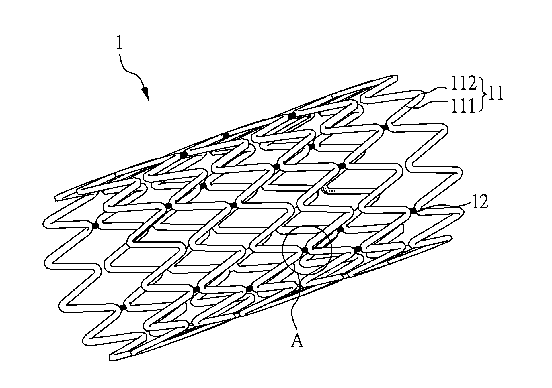
[0036]FIG. 1A and 1B respectively show a three-dimensional schematic diagram of the intravascular stent 1 and an enlarged view of its part A according to Example 1 of the present invention. As shown in FIG. 1A, the stent 1 comprises: a plurality of radially-expandable rings 11 arranged along a longitudinal axis, wherein each of the radially-expandable rings 11 respectively comprises a plurality of bar arms 111 and a plurality of crowns 112, and the adjacent crowns 112 are connected by the bar arms 111 therebetween; and a plurality of connectors 12 are disposed between and connecting the radially-expandable rings 11. As shown in FIG. 1B, the connectors 12 comprise helical structures.

[0037]In the present example, each of the helical structures is a single helical structure. However, a person skilled in the art can modify the helical structures into double helical structures or a combination thereof if needed, and the present invention is not limited thereto. In the intravascular stent...

example 2

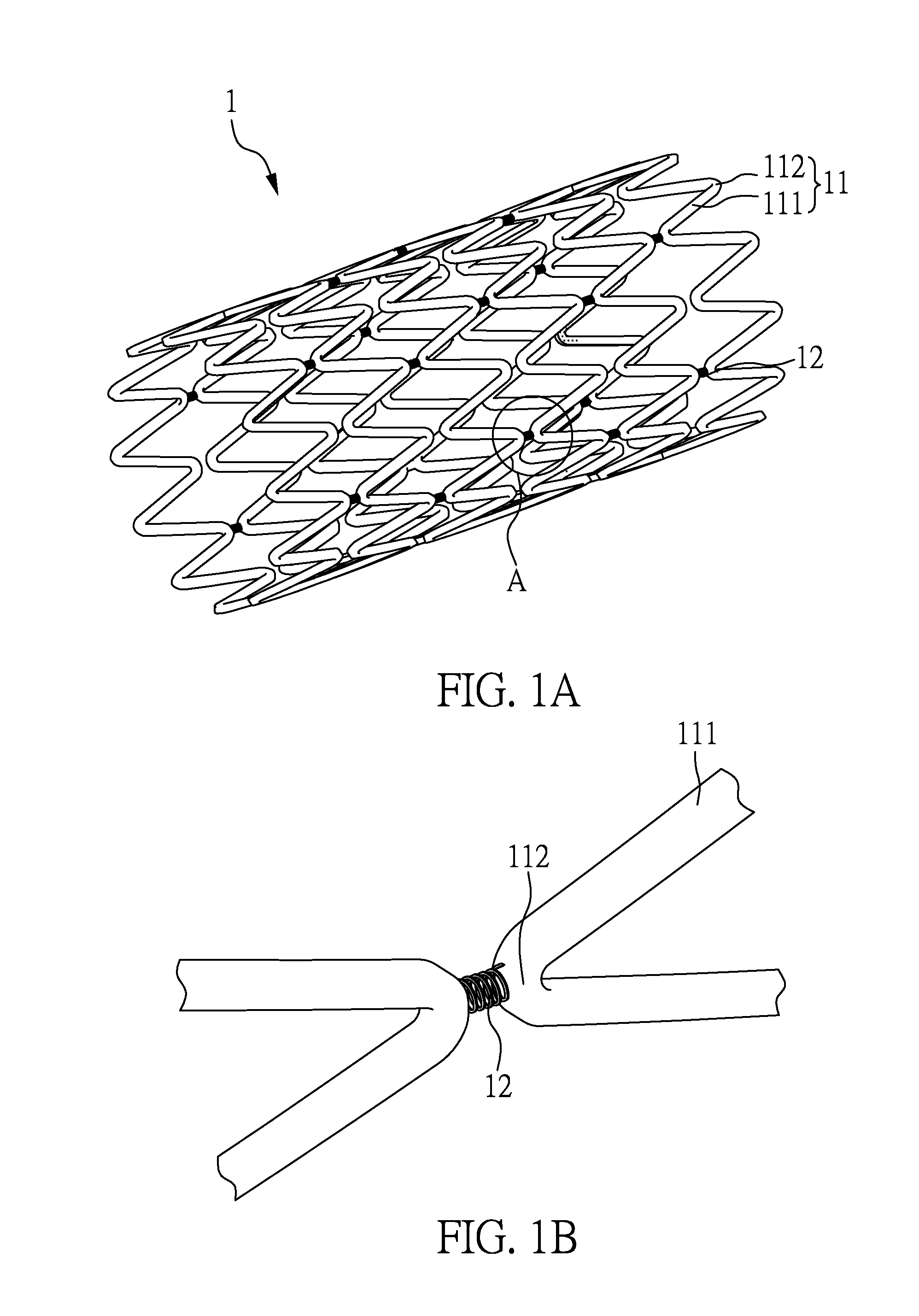
[0039]Please refer to FIG. 2A and FIG. 2B, respectively showing a three-dimensional schematic diagram of the stent 2 and an enlarged view of its part B according to Example 2 of the present invention.

[0040]Example 2 and Example 1 are substantially the same, except that the bar arms 211 of the stent 2 of Example 2 also comprise helical structures.

[0041]Therefore, as shown in FIG. 2A, the stent 2 comprises: a plurality of radially-expandable rings 21 arranged along a longitudinal axis, wherein each of the radially-expandable rings 21 respectively comprises a plurality of bar arms 211 and a plurality of crowns 212, and the adjacent crowns 212 are connected by the bar arms 211 therebetween; and a plurality of connectors 22 are disposed between and connecting the radially-expandable rings 21. As shown in FIG. 2B, the bar arms 211 and the connectors 22 comprise helical structures.

example 3

[0042]Please refer to FIG. 3A and FIG. 3B, which respectively show a three-dimensional schematic diagram of the stent 3 and an enlarged view of its part C according to Example 3 the present invention. As shown in FIG. 3A, the stent 3 comprises: a plurality of radially-expandable rings 31 arranged along a longitudinal axis, wherein each of the radially-expandable rings 31 respectively comprises a plurality of bar arms 311 and a plurality of crowns 312, and the adjacent crowns 312 are connected by the bar arms 311 therebetween; and a plurality of connectors 32 are disposed between and connecting the radially-expandable rings 31. As shown in FIG. 3B, the bar arms 311, the crowns 312, and the connectors 32 respectively comprise helical structures.

[0043]In the present example, the bar arms 311, the crowns 312, and the connectors 32 are composed of helical structures. In addition, the helical structures of the present example are single helical structures. However, a person skilled in the...


PUM

PropertyMeasurementUnit
Structureaaaaaaaaaa

Abstract

The present invention relates to a stent, comprising: a plurality of radially-expandable rings arranged along a longitudinal axis, wherein each radially-expandable ring may comprise a plurality of bar arms and a plurality of crowns, and adjacent crowns are connected by the bar arms therebetween; and a plurality of connectors between the radially-expandable rings for connecting such radially-expandable rings; wherein a cross-sectional shape of the bar arms, the crowns or the connectors may comprise helical structures, specific cross-sectional shapes, or a combination thereof. New stent manufacturing techniques, such as the 3D additive printing, could be used for making these proposed stents feasible.

Description

CROSS REFERENCE TO RELATED APPLICATION[0001]This application claims the benefits of Taiwan Patent Application Serial Number 103123943, filed on Jul. 11, 2014, the subject matter of which is incorporated herein by reference.BACKGROUND OF THE INVENTION[0002]1. Field of the Invention[0003]The present invention relates to an intravascular stent. More specifically, the present invention relates to an intravascular stent with helical structures, specific cross-sectional shapes, or any combination thereof prepared by a 3D additive printing method.[0004]2. Description of Related Art[0005]Vascular stent surgery has become a standard treatment for cardiovascular disease. A variety of stent-related inventions, such as drug-eluting stents, bioresorbable stents, and the like, are widely used for treating various vascular diseases, such as coronary artery, peripheral artery, and bile duct diseases.[0006]For the clinical application of the intravascular stent, important factors in stent design are...

Claims


Application Information

Patent Timeline
IPC IPC(8): A61L31/02A61F2/86A61L31/06B33Y80/00
CPCA61F2/86B33Y80/00A61F2230/0091A61L31/06A61F2002/828A61L31/022A61F2/88A61F2/915A61F2002/91541A61F2002/91575A61F2230/0021A61F2230/0089A61F2250/0018B33Y10/00C08L67/04
Inventor HSIAO, HAO-MINGCHEN, HSIN
Owner NAT TAIWAN UNIV
Why Eureka
Try Eureka