
Phase noise simulation model for pulse doppler radar target detection

Active Publication Date: 2016-01-14
ADVANCED TESTING TECH
View PDF3 Cites 9 Cited by
  • Summary
  • Abstract
  • Description
  • Claims
  • Application Information

AI Technical Summary

Benefits of technology

The present invention provides a method for calculating the performance of radar systems based on relevant parameters and phase noise at various carrier offset frequencies. This helps radar system designers to better understand and improve the performance of their systems.

Problems solved by technology

Phase noise has a significant impact on radar target detection, yet its impact is not always clearly understood by radar system operators and maintainers other than knowing that low system phase noise within a radar system is critical to mission capability.

Method used


Image

  • Phase noise simulation model for pulse doppler radar target detection
  • Phase noise simulation model for pulse doppler radar target detection
  • Phase noise simulation model for pulse doppler radar target detection

Examples


Embodiment Construction

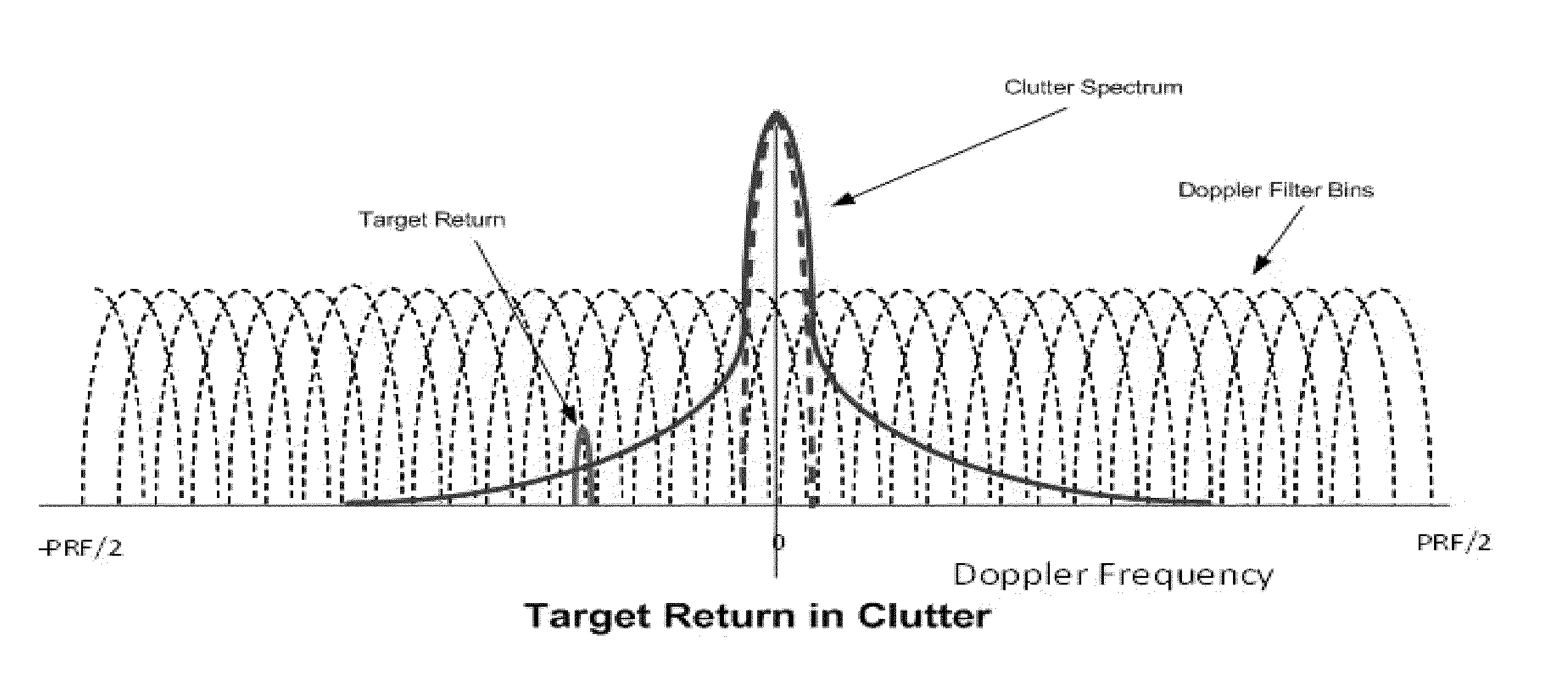
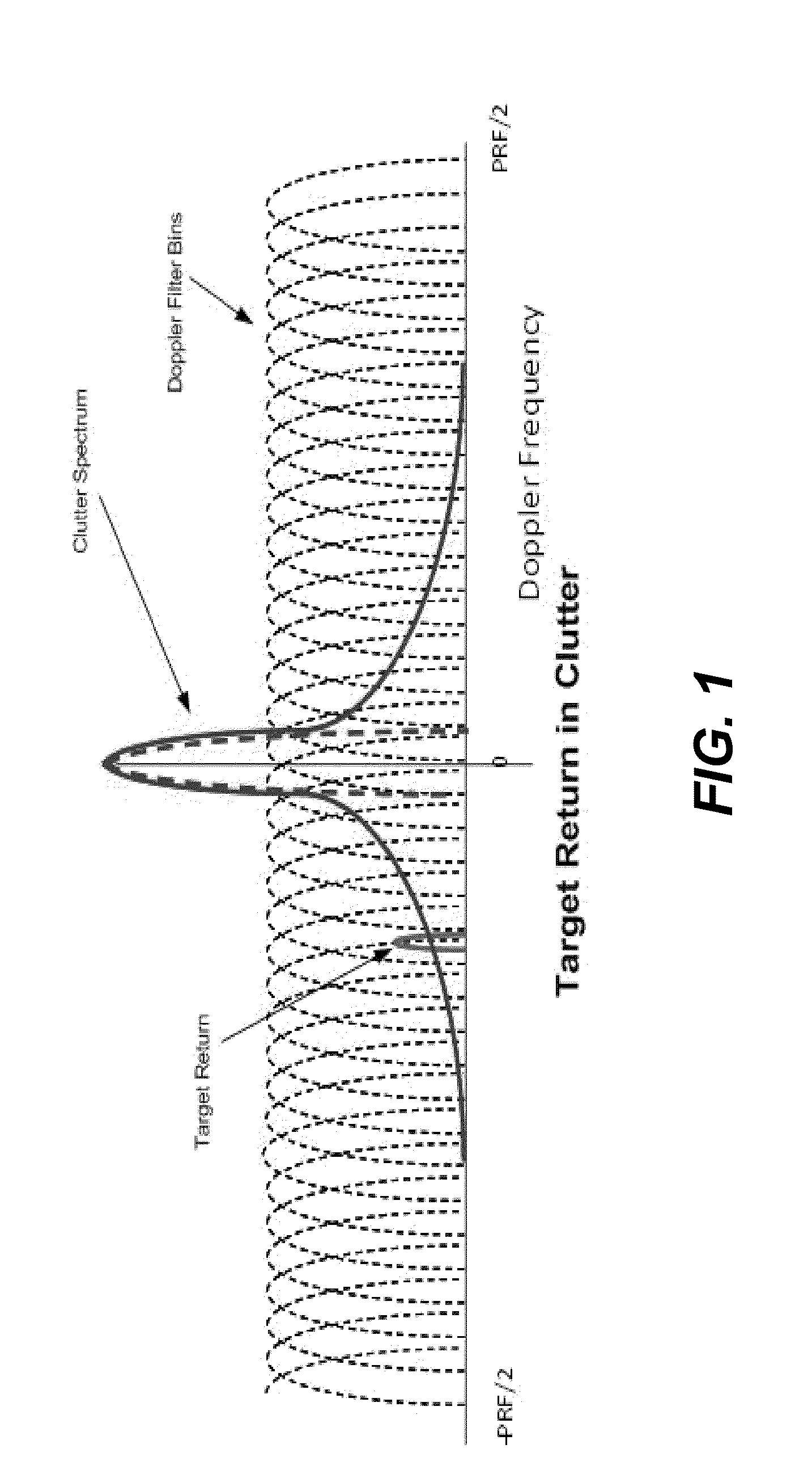
[0019]Pulse Doppler signal processing generally involves implementing the FFT algorithm in a signal processor, which develops a bank of filters, extending from −PRF / 2 to +PRF / 2 (PRF being the pulse repetition frequency). The target velocity determines the Doppler bin in which the target will be found. The stationary surface clutter (land or sea) will be in a different Doppler filter, so the target and clutter can be separated, even though the clutter signal may be much larger than the target signal (see FIG. 1). Not only does the Doppler filter allow the system to separate low velocity returns, which include most ground and sea clutter, but the system can also determine the target velocity. The received signal from each bin is collected and placed into a matrix for processing through the appropriate signal processing conditions and the results presented to an operator of the radar system. The system of Doppler filter bins and constant false alarm rate (CFAR) adaptive thresholds dete...


PUM


Abstract

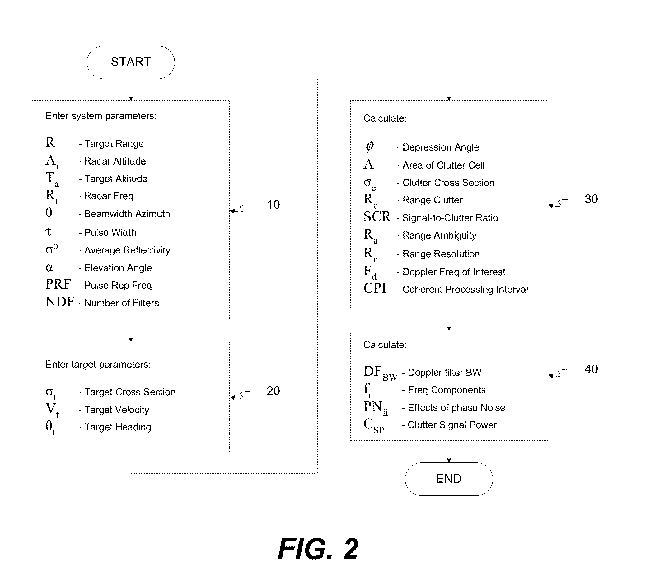
Method for generating a model of the effect of phase noise during use of a Doppler radar system including calculating, using a processor, an initial signal-to-clutter ratio (SCR) representing a ratio of power received from echoes from a target by the radar system to power resulting from clutter reflection received by the radar system. The initially calculated SCR is modified as a function of a range ambiguity and range resolution. A Doppler frequency of interest is calculated based on velocity of a target, target heading and radar frequency, along with a Doppler filter bandwidth, frequency components and a measure of clutter signal passing through the Doppler filter of interest by summing products of the phase noise for each frequency by the Doppler filter bandwidth. This measure indicates effectiveness of target detection by the Doppler radar system as a function of distance.

Description

CROSS-REFERENCE TO RELATED APPLICATION[0001]This application claims priority under 35 U.S.C. §119(e) of U.S. provisional patent application Ser. No. 62 / 023,362 filed Jul. 11, 2014, which is incorporated by reference herein.FIELD OF THE INVENTION[0002]The present invention relates generally to computer simulation and modeling of phase noise within a pulse Doppler radar target system and the effect it has with respect to overall system performance.[0003]The present invention also relates to a method for generating a model of phase noise with a pulse Doppler radar target system and using the generated model.[0004]The present invention also relates to a method for designing, configuring or analyzing a pulse Doppler radar system to obtain a more accurate radar response by reducing the effect of clutter return via appropriate selection of the components of the radar system and analysis of the operation of various configurations of radar components relative to clutter.BACKGROUND OF THE INV...

Claims


Application Information

Patent Timeline
IPC IPC(8): G06F17/50G01S7/02G06F17/10
CPCG06F17/5009G06F17/10G01S7/02G01S7/40G01S13/5244G06F30/20
Inventor MINASSIAN, SHAHENBAKER, JOHN L.LEVI, ELI
Owner ADVANCED TESTING TECH
Learn More