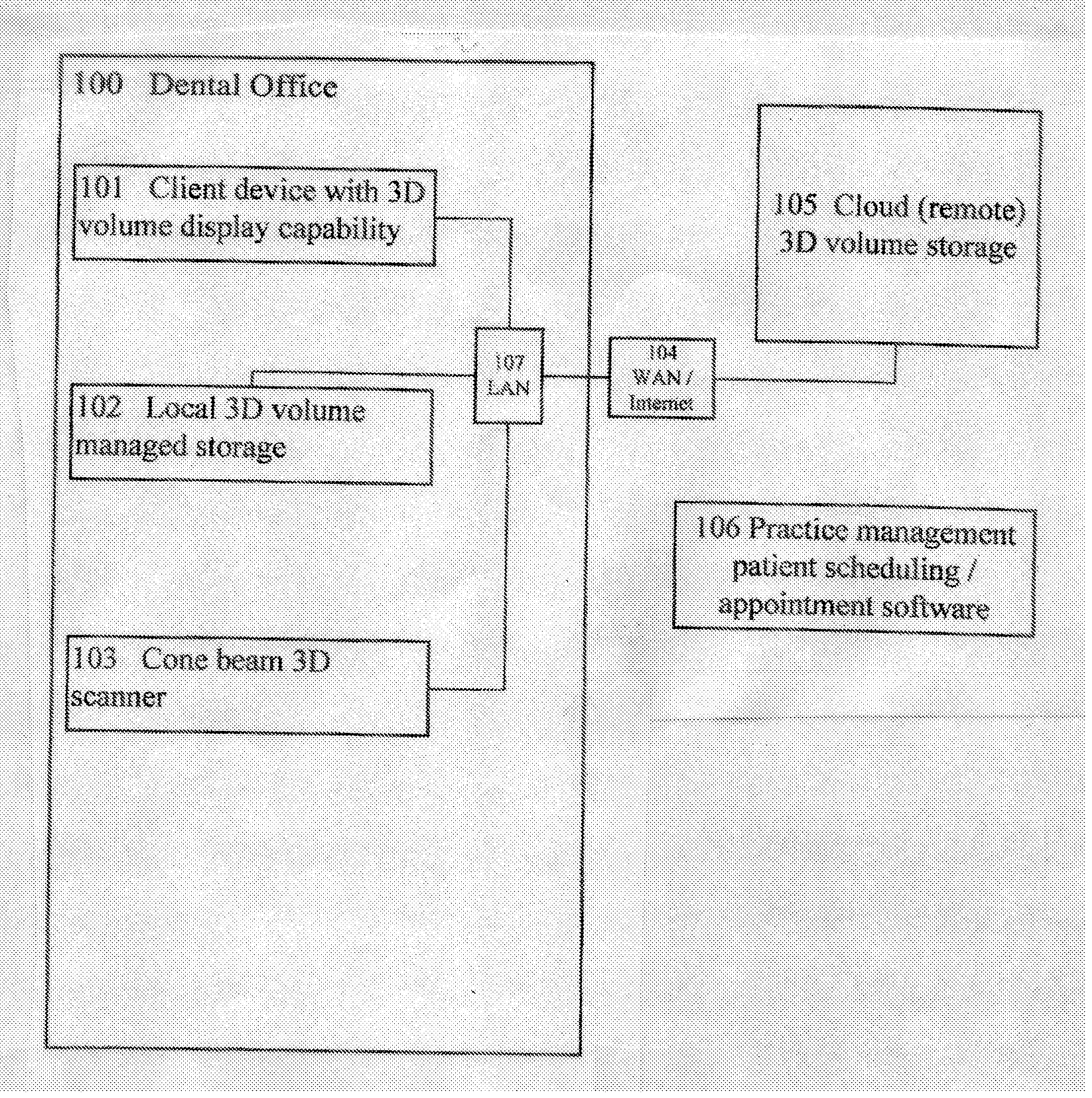
In a 3D equipped dental office / environment where remote storage is desired to be used for storing and sharing 3D volumes, it is not currently feasible because the remote storage and / or application are operated via a bandwidth limited connections such as a cable or DSL internet connection which are inherently too slow to upload and download the 3D volumes for
processing nearly real time which is required in the dental
workflow.
Likewise the bandwidth available is also normally too slow to send the high quality rendered preview results from the
application server in semi-real-time to display on the
client.
The above remote application, remote storage and bandwidth issue lead to 3D
dental imaging systems not being able to be implemented to work well with remote storage.
The hardware and software involved with these systems are expensive, and require complicated and
time consuming installations.
Also, there can be limitations on the number of simultaneous users that can be accommodated.
Generally the
information technology (IT) department of the center which purchased the system must be heavily involved, which can strain resources and complicate the installation and maintenance process.
The transmission of
DICOM image files that are transmitted in a
DICOM communication session may often include various errors, including data errors and
data format errors, which complicate one's ability to receive and process a
DICOM image file.
Moreover, certain older CT and MRI devices may incorrectly populate DICOM data fields.
Too often, discovery of such errors occurs during
processing of a DICOM image file, which contributes increased
frustration and associated costs.
Often, similar or the same errors are repeated by the same sending DICOM service class user.
Similarly, the
data structure for the filing of patient studies may vary from site to site, making
data transport challenging and often having to involve non-medical related parties such as system administrators to complete the transfer.
In many cases secure private networks, such as VPNs are utilized between the facilities sharing the medical images in order to preserve patient
confidentiality and meet HIPAA requirements, thus limiting the ability to share image files.
In certain situations, however, the particular manner in which the images are made available to physicians and their patients introduces obstacles to timely and accurate diagnoses of
disease.
These obstacles generally relate to the fact that each manufacturer of a
medical imaging system uses different and proprietary formats to store the images in digital form.
Although it is typically possible to “export” the images from a proprietary
workstation to an industry-standard format such as “
Digital Imaging Communications in
Medicine” (DICOM), Version 3.0, several limitations remain as discussed subsequently.
The specialist physician, however, typically has not performed a clinical history and
physical examination of the patient and often is not aware of the patient's other test results.
Although this approach does allow for expert interpretation of the images by the specialist physician, several limitations are introduced for the
primary physician and for the patient, such as, for example: (1) The
primary physician does not see the images unless he travels to another department and makes a request; (2) It is often difficult to find the images for viewing because there typically is no formal procedure to accommodate requests to show the images to the
primary physician; (3) Until the written report is forwarded to the primary physician's office, it is often difficult to determine if the images have been interpreted and the report generated; (4) Each proprietary
workstation requires training in how to use the software to view the images; (5) It is often difficult for the primary physician to find a
technician who has been trained to view the images on the proprietary workstation; (6) The workstation software is often “upgraded” requiring additional training; (7) The primary physician has to walk to different departments to view images from the same patient but different modalities; (8) Images from the same patient but different modalities cannot be viewed side-by-side, even using proprietary workstations; (9) The primary physician cannot show the patient his images in the physician's office while explaining the diagnosis; and (10) The patient cannot transport his images to another physician's office for a second opinion.
Teleradiology does not, however, allow for the examination of the images from any site other than the central location, precluding examination of the images by the primary physician and the patient.
One such limitation is the bandwidth of current Internet connections which, because of the
large size of medical images, result in transfer times which are unacceptably long.
The problem of bandwidth can be addressed by compressing the image data before transfer, but compression typically involves loss of
diagnostic information.
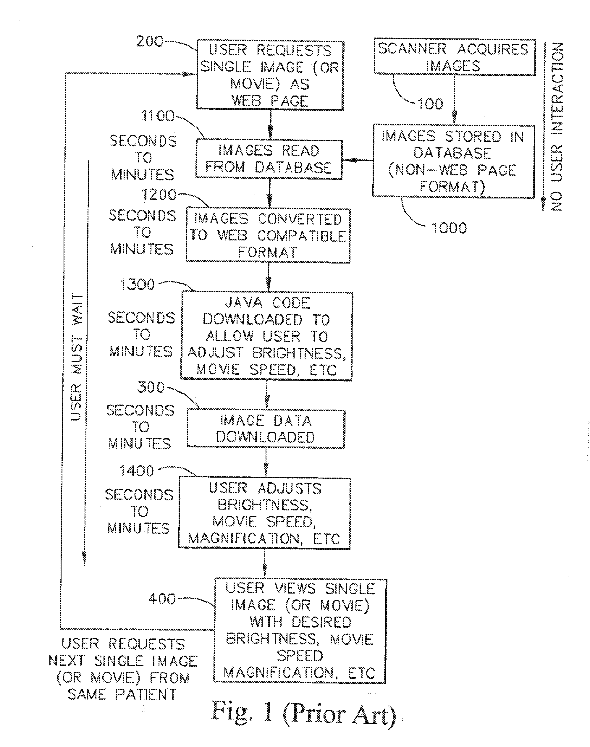
In addition, due to the size of the images the time required to process image data from an original format to a format which can be viewed by Internet browsers is considerable, meaning that systems designed to create Web Pages “
on the fly” introduce a
delay of seconds to minutes while the person requesting to view the images waits for the data to be processed.
Workstations allow images to be reordered or placed “side-by-side” for viewing, but again, an Internet system would have to create new Web Pages “
on the fly” which would introduce further delays.
There are several disadvantages to using “
Java” to manipulate the image data.
First, the user must wait additional time while the “
Java” code is downloaded.
Third, the user must wait while the “
Java” code processes the image data, which is slow because the image files are large.
Fourth, “Java” code is relatively new and often causes browsers to “
crash.” Finally, due to the “crashing” problem “Java” programmers typically only test their code on certain browsers and computers, such as Microsoft Explorer on a PC, precluding widespread use by owners of other browsers and other computer platforms.
The approach of Wood, however, creates Web Pages “
on the fly,” meaning that the user must wait for the
image processing to complete.
In addition, even after processing of the image data into a
Web Page the approach of Wood does not provide for processing the images in such a way that excessive
image transfer times due to limited bandwidth are addressed or provide for “brightness / contrast” to be addressed without loss of
diagnostic information.
In addition, the approach of Wood is limited to
ultrasound images generated by scanners manufactured by a single company, and does not enable viewing of images from modalities other than
ultrasound.
The approach of Wood, however, creates Web Pages “on the fly,” meaning that the user must wait for the
image processing to complete.
In addition, even after processing of the image data into a
Web Page the approach of Wood does not provide for processing the images in such as way that excessive
image transfer times due to limited bandwidth are addressed or provide for “brightness / contrast” to be addressed without loss of diagnostic information.
In addition, the approach of Wood is limited to
ultrasound images generated by scanners manufactured by a single company, and does not enable viewing of images from modalities other than ultrasound.
Serial processing of image data “on the fly” combined with extensive user interaction results in a slow, expensive, and unstable system.
Steps 1000-1400 result in extensive user interaction which results in the system being slow, expensive and unstable.
Serial processing of image data “on the fly” combined with extensive user interaction results in a slow, expensive, and unstable system.
Steps 1000-1400 result in extensive user interaction which results in the system being slow, expensive and unstable.
This, in turn, is dependent on the degree to which the surface under scrutiny has undercuts and shadowing features which would result in the failure of the imaging device to detect the projection pattern.
However as the angle increases, the presence of undercuts and shadowing features will block the reflected pattern and prevent capture of the pattern and subsequent three-
dimensional analysis of those portions of the surface.
The larger the mirror, the more difficult in-vivo scanning becomes, so some trade-off between size and utility for in-vivo scanning exists.
Generally, access to a private cloud is limited to that single organization or its affiliates.
For example, some users with certain roles can only access some of the tools provided by the system.
It is noted that three 3-d models can still be generated from a lesser or insufficient number of medical scans, although such 3-d models will not be accurate enough to generate patient-specific alignment guides that mirror the corresponding joint surfaces of the specific patients.
Dental offices are pressured to shrink costs and increase profitability in the midst of increasing IT costs caused by advances in technology.
One of largest challenges facing today's dental professionals, and
dental offices in general, is maintaining the software and hardware needed to operate a dental office.
Such non-dental specialized hiring increases the overall cost of running a dental practice.
Quickly, it becomes difficult to scale the respective infrastructure in a cost
effective method.
Another challenge to operating an effective dental practice is integrating the amount of information generated by the different number of software applications used.
Usually two or more application systems are used to accomplish all these necessary functions and such application are becoming more complex.
Such complexity requires more training and / or additional staff to simply operate the applications.
Even more challenging is retrieving data from each system and integrating this data so that comprehensive picture the practice may be obtained.
The need to have these third parties interact with the internal staff of the dental office is a security risk, is known to be inefficient and requires local dental professional / management assistance during the process.
As an example, an orthodontist operating out of an orthodontic office may not be equipped to render one or more specific examinations, such as a periodontal examination, a
dental examination, a bite examination, a temporo-mandibular joint or “TMJ” examination, a facial examination, and a cephalo-metric examination.
Moreover, even if such orthodontists can confidently and competently carry out such varied examinations, they may not be well-equipped to carry out all the recommended treatments.
Moreover, a working practitioner in a field such as
orthodontics, who may have a busy patient load, may not always be apprised of the newest
treatment options in other fields, such as maxillofacial and orthognathic
surgery or TMJ conditions.
It is also a possibility that a practitioner may not be well-connected or personally acquainted with other practitioners in other
specialty areas, and therefore may not be able to confidently make referrals.
Indeed, this can involve faxing records, making numerous telephone calls, writing letters, and the like, all of which require valuable time and effort on the part of the referring practitioner and his or her staff.
A downside to these paper files is that they must be stored when not in use (which is the vast majority of the time), located and provided to the practitioner in advance of a patient appointment, and then returned afterwards.
This is cumbersome and is typically handled by letter, fax and / or email, and requires additional effort and expense on the practitioner and his or her staff, for which the referring physician is often not compensated.
As
medical software becomes more sophisticated and universal, integration among software packages becomes more important and more challenging.
One of the challenges of the increased use of these different software packages is that they are generally created and supported by different vendors, and do not interoperate or “talk” to each other well.
Currently this is not practical within any of the EMR or EHR software packages.
Some EMR software allows the user to view a
static image, such as an X-
ray, but the user is not able to manipulate the image, or view a more advanced image such as a 3D image with appropriate interactive tools.
Software packages exist for doing this more advanced image processing, but currently they are not integrated with EMR or other
medical software platforms.
The same lack of integration exists for clinical trials, and other
medical software packages also.
This means that the viewer and / or analyzer of the data generally do not know the identity of the individual patients / participants.
Also, the appropriate tools need to be shown and inappropriate tools hidden.
Based on this analysis, the appropriate views and / or tools can be made visible to the user, and inappropriate views and / or tools can be hidden.


