
Organic light emitting display device and its packaging method

a light-emitting display device and organic technology, applied in the direction of thermoelectric device junction materials, semiconductor devices, electrical devices, etc., can solve the problems of slow internal thermal conduction of organic light-emitting diodes, and affecting the use life of flat-panel display devices. , to achieve the effect of avoiding damage to organic light-emitting display devices, reducing space occupation, and reducing negative influen

Active Publication Date: 2016-01-14
BOE TECH GRP CO LTD
View PDF1 Cites 7 Cited by
  • Summary
  • Abstract
  • Description
  • Claims
  • Application Information

AI Technical Summary

Benefits of technology

The present disclosure provides an organic light emitting display device that has good packaging effects, tightness, and heat dissipation performance. The device utilizes an insulating carbon nanotube layer that can quickly transfer heat from the organic light emitting diode to the metal cover plate without current conducting. The carbon nanotube also contains a desiccant to prevent water vapor damage and reduces space occupation. The adhesive used for bonding the cover plate and substrate has a larger contact area and avoids poor packaging effects due to desiccant dispersion. Overall, the device has better heat dissipation, sealing, and is simpler to manufacture.

Problems solved by technology

With the extended period of usage, heat might accumulate in the device of the display apparatus due to slow thermal conduction.
If the temperature of the device exceeds the tolerable temperature of the organic light emitting diode material, it might cause vaporization, deterioration or other harmful phenomenon to the material of the organic light emitting diode, thereby affecting the usage life of the flat panel display apparatus.
Both of the materials have small thermal conductivities, poor thermal conduction performance, resulting in slow internal thermal conduction in the organic emitting diode, which is disadvantageous to the long term usage of the organic light emitting display device.
However, in the two methods, the usage of lots of desiccants might degrade the adhesion between the packaging adhesive and the cover pate, the organic light emitting diode, and the substrate, thereby influence the package effect.
As to chiral different carbon tubes, doping, absorbance and vacancy defects can influence the thermal conduction function, wherein the armchair carbon tube is most sensitive to doping defects, causing its coefficient of thermal conductivity to decrease dramatically.

Method used


Image

  • Organic light emitting display device and its packaging method
  • Organic light emitting display device and its packaging method
  • Organic light emitting display device and its packaging method

Examples


Embodiment Construction

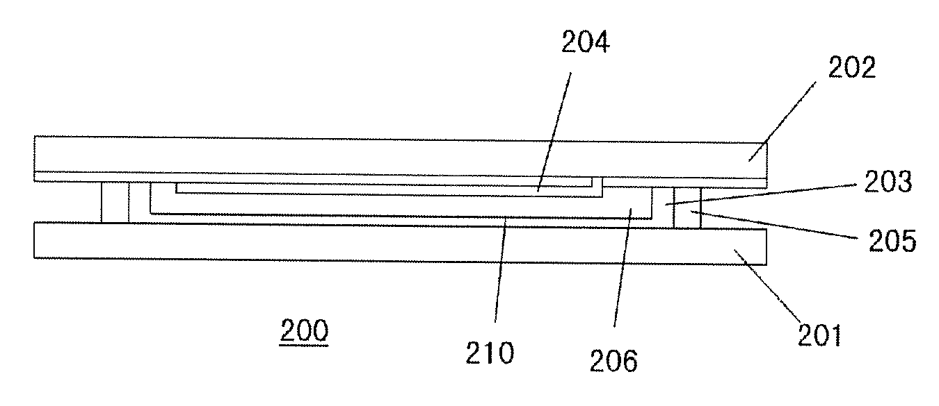
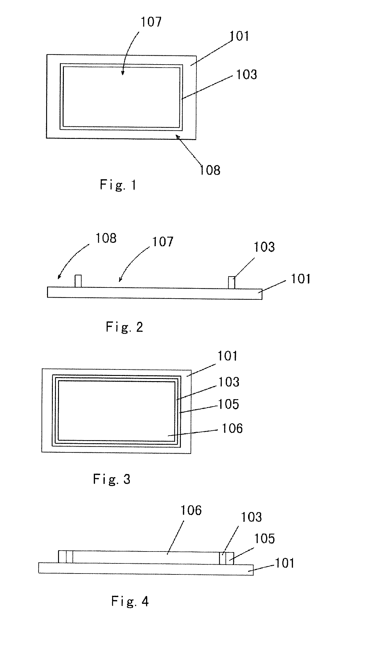
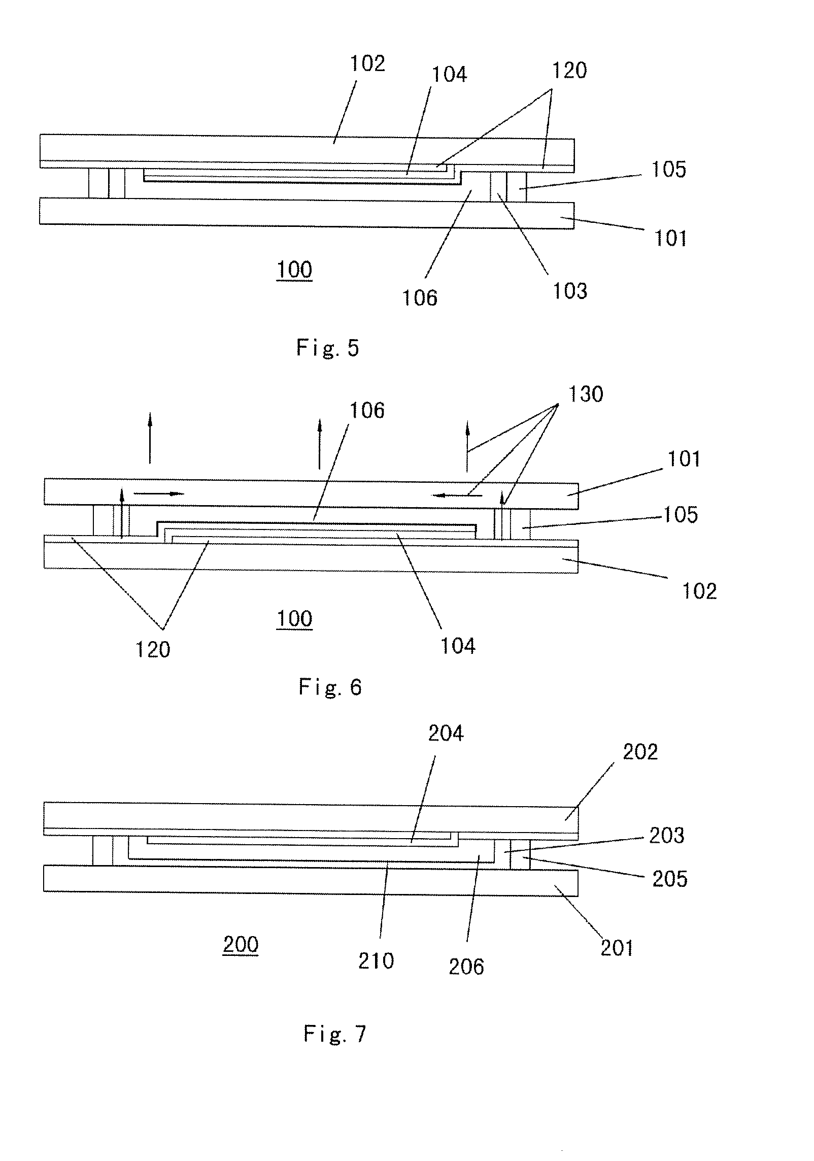
[0026]Referring to FIG. 5, it shows an organic light emitting display device 100 according to the first embodiment of the present disclosure, which comprises a cover plate 101, a substrate 102, a carbon nanotube layer 103, an organic light emitting diode 104, packaging adhesive 105 and filling adhesive 106. The organic light emitting diode 104 and the substrate 102 can be packaged on the cover plate 101 by the packaging adhesive 105 and the filling adhesive 106 applied around the carbon nanotube layer 103.

[0027]Referring to FIG. 1, FIG. 2, FIG. 3, FIG. 4 and FIG. 5 simultaneously, the specific packaging process of the organic light emitting display device 100 of the first embodiment of the present disclosure comprises the following steps:

[0028]first, providing a metal cover plate 101, whose material is aluminum or copper;

[0029]creating a single-walled carbon nanotube layer 103 with insulating property uniformly modified with aluminum oxide (Al2O3) on the cover plate 101 by a chemica...


PUM


Abstract

The present disclosure relates to an organic light emitting device, which includes: a cover plate, a substrate and an organic light emitting diode. The cover plate has a carbon nanotube layer thereon. The organic light emitting diode and the substrate are packaged on the cover plate by adhesive applied around the carbon nanotube layer. The organic light emitting display device provided by the present disclosure has a good packaging effect, a good tightness and a good heat dissipation performance.

Description

FIELD OF THE DISCLOSURE[0001]The present disclosure generally relates to the technical field of organic electroluminescent displays, and in particular relates to an organic light emitting display device and its packaging method.BACKGROUND OF THE DISCLOSURE[0002]Organic electroluminescent diode (OLED), also known as organic light emitting diode, emits light based on the following principle: current is applied to certain organic material which can convert electric energy into luminous energy so as to emit light. Organic light emitting diode has the characteristics of active light emitting, high contrast, and low power consumption and the like, and has been widely used in the field of new generation flat panel display.[0003]The flat panel display apparatus using organic light emitting diode will produce heat in usage. With the extended period of usage, heat might accumulate in the device of the display apparatus due to slow thermal conduction. If the temperature of the device exceeds t...

Claims


Application Information

Patent Timeline
Patent Type & Authority Applications(United States)
IPC IPC(8): H01L51/52H01L51/56
CPCH01L51/5246H01L51/56H01L51/5259H01L51/529H10K59/874H10K59/8794H10K59/8721H10K59/8722H10K50/8426H10K50/87H10K71/00H10K50/846H10K50/8423
Inventor LUO, CHENGYUANWANG, CHUNJAN
Owner BOE TECH GRP CO LTD
Learn More