Antenna, printed circuit board, and wireless communication device

a printed circuit board and wireless communication technology, applied in the direction of antennas, antenna details, basic electric elements, etc., can solve the problems of difficult downsizing of such antennas and increase in manufacturing costs, and achieve the effect of low cos

Active Publication Date: 2016-01-14
NEC CORP +1
View PDF3 Cites 9 Cited by
  • Summary
  • Abstract
  • Description
  • Claims
  • Application Information

AI Technical Summary

Benefits of technology

The present invention provides a small and low-cost antenna that can be used in printed circuit boards and wireless communication devices. This makes it easier to realize the technical effects of the invention, which include improved efficiency and reduced costs.

Problems solved by technology

However, since an antenna of this kind needs to be as large as approximately ¼ to ½ of its wavelength in principle, the downsizing of such antennas has been difficult.
In addition, a matching circuit is required for impedance matching between antennas and feeding lines, which causes a problem of an increase in manufacturing cost.

Method used


Image

  • Antenna, printed circuit board, and wireless communication device
  • Antenna, printed circuit board, and wireless communication device
  • Antenna, printed circuit board, and wireless communication device

Examples


first exemplary embodiment

[0062]An antenna 10 according to a first exemplary embodiment of the present invention is described below with reference to the drawings.

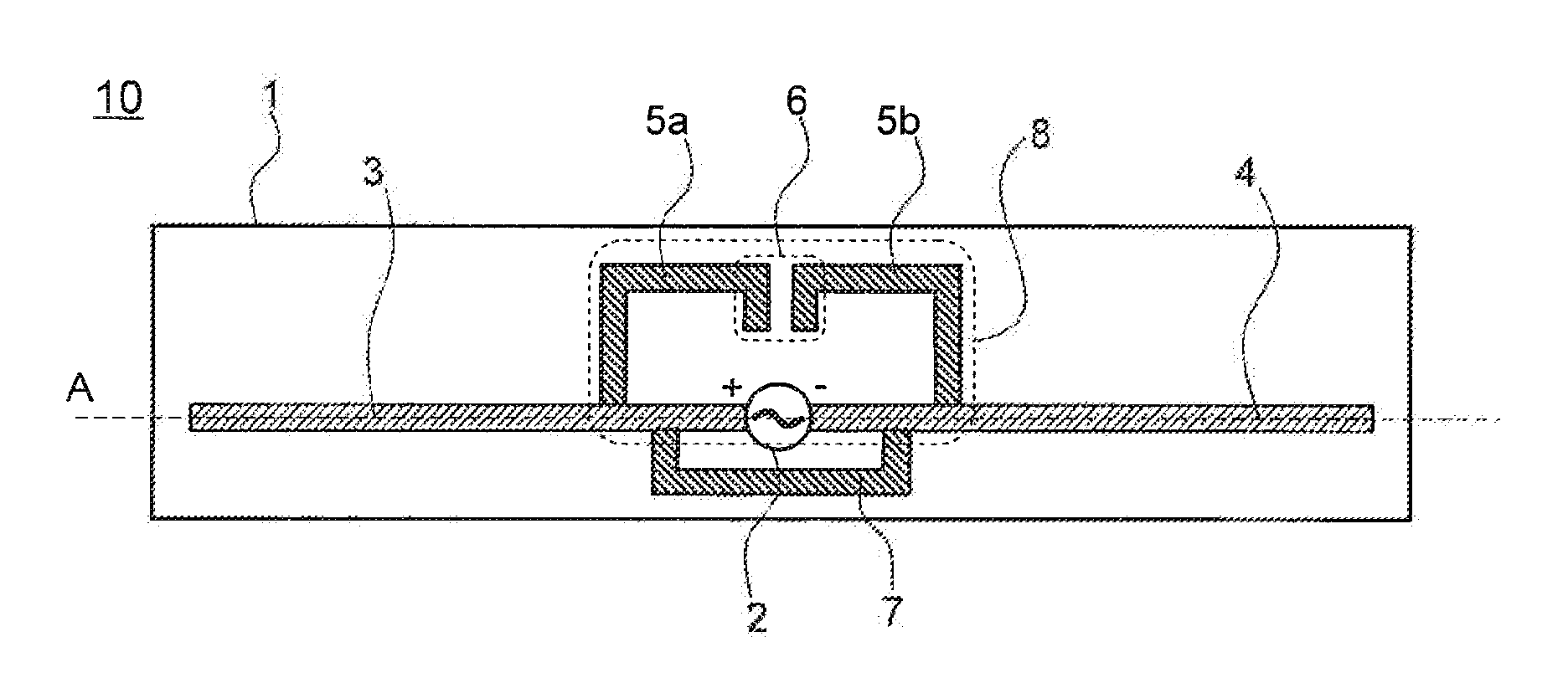
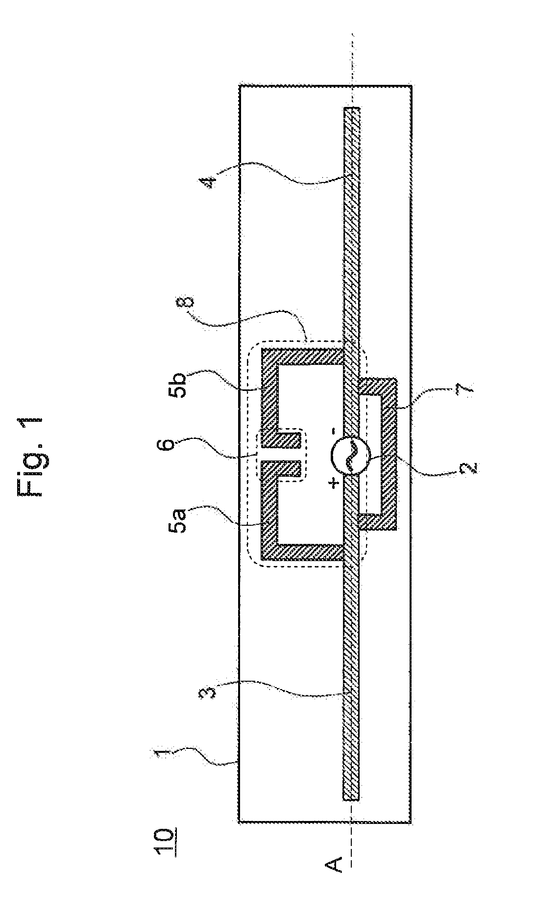
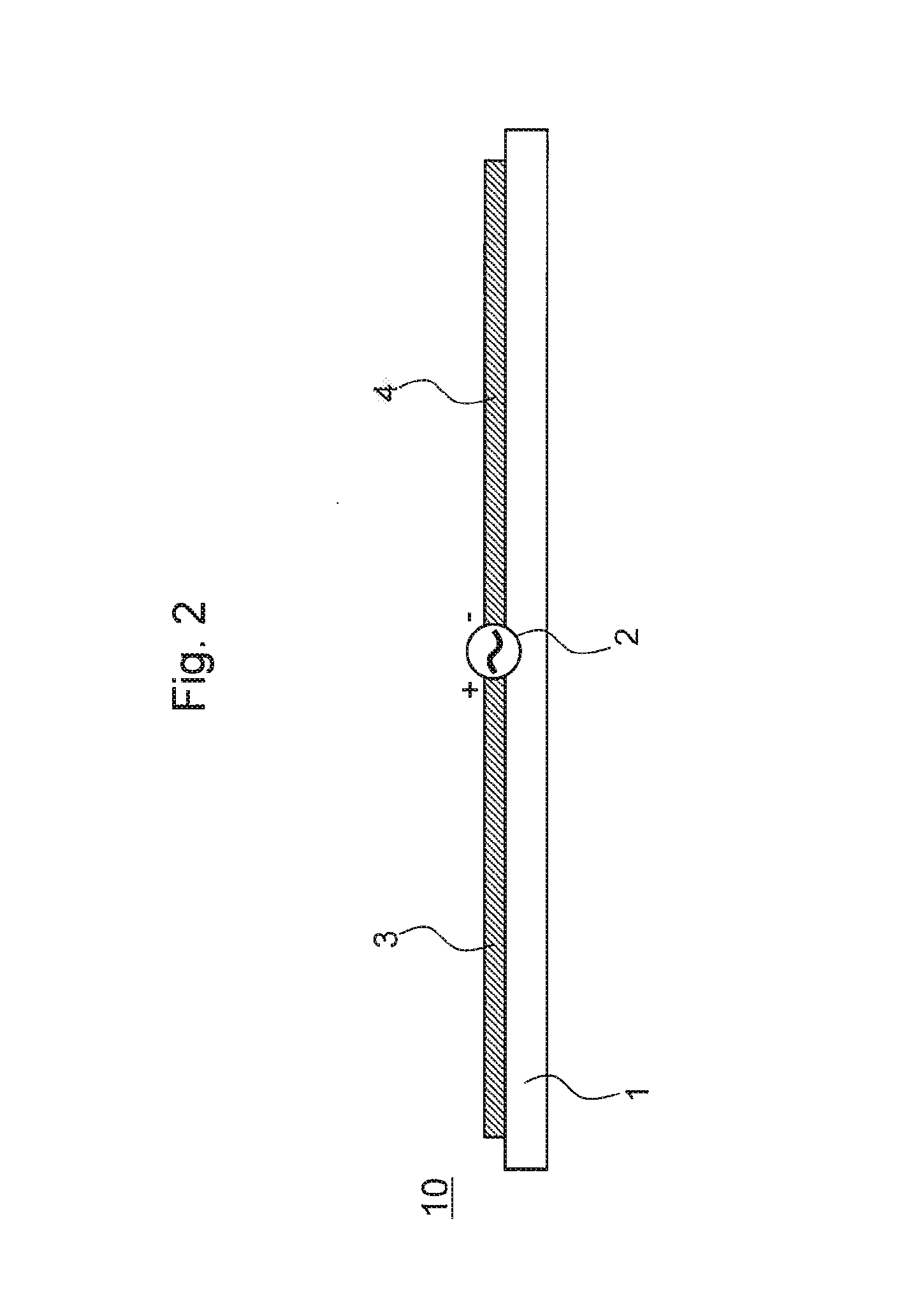
[0063]FIG. 1 is a top view illustrating a configuration of the antenna 10 according to the first exemplary embodiment. FIG. 2 is a cross-sectional view of the antenna 10 taken along a dotted line A in FIG. 1. The antenna 10 according to the first exemplary embodiment is formed on a surface layer of a printed circuit board 1 and includes an antenna feeding point 2, a first radiant element 3, and a second radiant element 4. The antenna feeding point 2 includes two terminals (+terminal, −terminal). The first radiant element 3 is a linear conductive pattern connected to the +terminal of the antenna feeding point 2. The second radiant element 4 is a linear conductive pattern connected to the terminal of the antenna feeding point 2. The antenna feeding point 2 is connected to a transmission line that transmits radio signals from an unillustrated radio ci...

second exemplary embodiment

[0082]An antenna 20 according to a second exemplary embodiment of the present invention is described below with reference to the drawings. The second exemplary embodiment is the same as the antenna 10 according to the first exemplary embodiment except for the following respect. Note that the same reference signs as those of the antenna 10 according to the first exemplary embodiment are assigned to the common constituent elements, and description thereof is omitted.

[0083]The first exemplary embodiment illustrates, as an example, a case in which the connection element 7 has a long and narrow linear shape. However, the connection element 7 may have any shape as long as having one end connected to part of the first radiant element 3, having the other end connected to part of the second radiant element 4, and electrically connecting the first radiant element 3 and the second radiant element 4 so that the split 6 is not included in the area surrounded by the connection element 7, the firs...


PUM


Abstract

An antenna (10) includes: a first radiant element (3) and a second radiant element (4), which are connected to an antenna feeding point (2); a first branch part (5a), one end of which is connected to the first radiant element (3) at a position not corresponding to an end portion of the first radiant element (3); a second branch part (5b), one end of which is connected to the second radiant element (4) at a position not corresponding to an end portion of the second radiant element (4); and a connection element (7), which connects part of the first radiant element (3) and part of the second radiant element (4). A different end of the first branch part (5a) and a different end of the second branch part (5b) face each other and form a capacitor part. The capacitor part is positioned outside the area surrounded by the connection element (7), the first radiant element (3), and the second radiant element (4). Part of the first radiant element (3), part of the second radiant element (4), the first branch part (5a), the second branch part (5b), and the capacitor part form a split ring resonator (8).

Description

TECHNICAL FIELD[0001]The present invention relates to a small antenna, and a printed circuit board and a wireless communication device each of which includes the antenna.BACKGROUND ART[0002]With regard to electronic devices having communication functions (wireless communication devices), it is constantly desired to downsize the entire devices. In addition, the spread of MIMO (multiple-input and multiple-output) communication systems, which enable increase in capacity by simultaneously using multiple antennas, is leading to an increase in the number of antennas installed in a wireless communication device. For these reasons, reduction in both size and cost of antennas installed in wireless communication devices is strongly desired.[0003]In general, antennas such as dipole antennas and monopole antennas, which have low directivities and are capable of emitting radio waves in a wide range of directions, and inverted L antennas, which are a variation thereof, are used in small wireless ...

Claims


Application Information

Patent Timeline
Patent Type & Authority Applications(United States)
IPC IPC(8): H01Q1/36H04B1/40
CPCH04B1/40H01Q1/36H01Q1/243H01Q9/285
Inventor TOYAO, HIROSHIUCHIDA, JUN
Owner NEC CORP
Why Eureka
Try Eureka