Electrical Connector Plug

a technology of electrical connectors and connectors, applied in the direction of coupling devices, two-part coupling devices, electrical apparatus, etc., can solve the problems of reducing the signal to noise ratio (s/n) ratio during transmission operations, difficult replacement or fixing by itself, and increasing complexity and compactness in the arrangement of conductive terminals. , to achieve the effect of reducing the signal transmission attenuation, enhancing the s/n ratio, and reducing the impedance through the high frequency

Active Publication Date: 2016-01-14
ADVANCED CONNECTEK INC
View PDF10 Cites 26 Cited by
  • Summary
  • Abstract
  • Description
  • Claims
  • Application Information

AI Technical Summary

Benefits of technology

[0012]The electrical connector plug disclosed in the present invention is characterized in that the signal transmission terminals are alternatively installed on the USB plug and also provides an electrical conductive plate of metal materials such that, by means of the impedance drop segment, in addition to the original internal impedance, a parallel connection electrical resistance can be further generated in each of the high frequency signal terminals so that the transmission impedance through the high frequency signal terminals can be reduced because of the capacitive effect created between the high frequency signal ter

Problems solved by technology

However, as the USB socket is typically built inside the 3C product, once damaged, users may find it is difficult to replace or fix it by themselves.
However, signal transmission volumes transferred through USB Type-C continuously and significantly ascend, so frequency of transmission signals needs to be elevated; in addition, due to a greater number of conductive terminals in USB Type-C and space-limited integral perspective size thereof, the complexity and compactness in the arrangement of the conductive terminals inevitably become more challenging.
In particular, because of the increase in transmission signal frequency and shortened intervals between the signal transmission terminals, the possibility of crosstalk among such terminals becomes signific

Method used


Image

  • Electrical Connector Plug
  • Electrical Connector Plug
  • Electrical Connector Plug

Examples


first embodiment

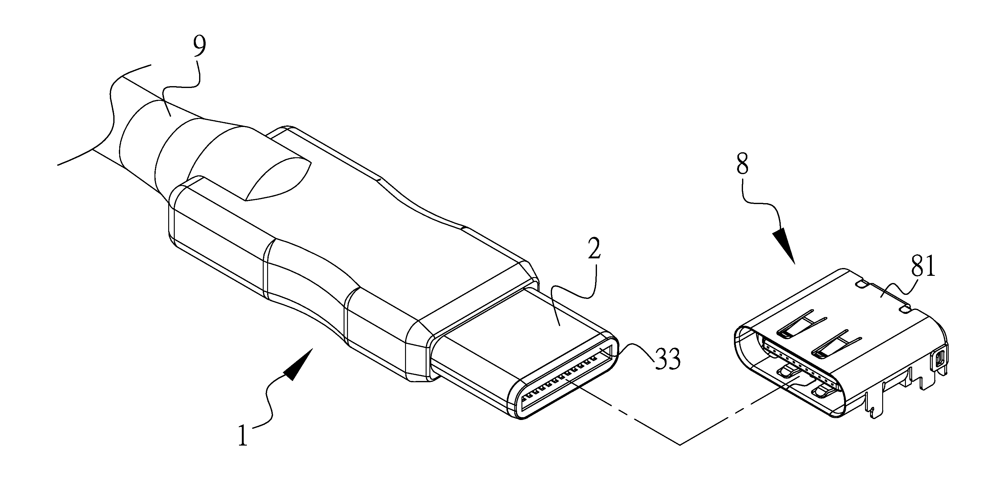
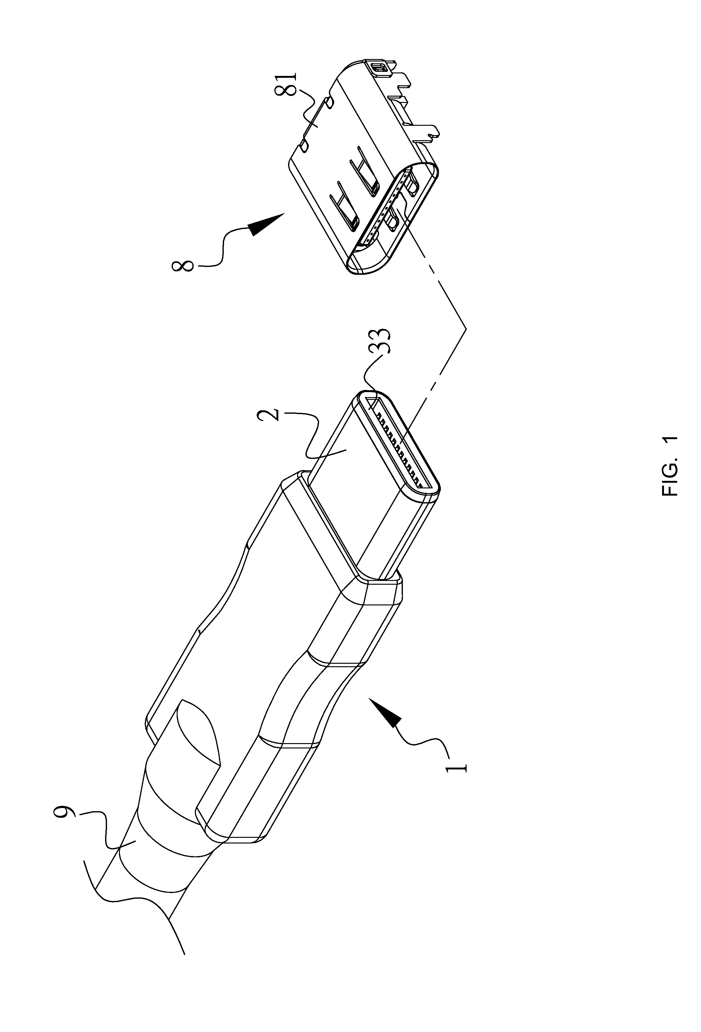
[0031]the present invention is exemplified with an electrical connector assembly. Referring to FIGS. 1 to 9, the electrical connector assembly is exemplified with a USB connector assembly, comprising an electrical connector socket 8 exemplified as a USB socket, and an electrical connector plug 1 capable of operating conjunctively with an electrically conductive line 9 and exemplified as a USB plug.

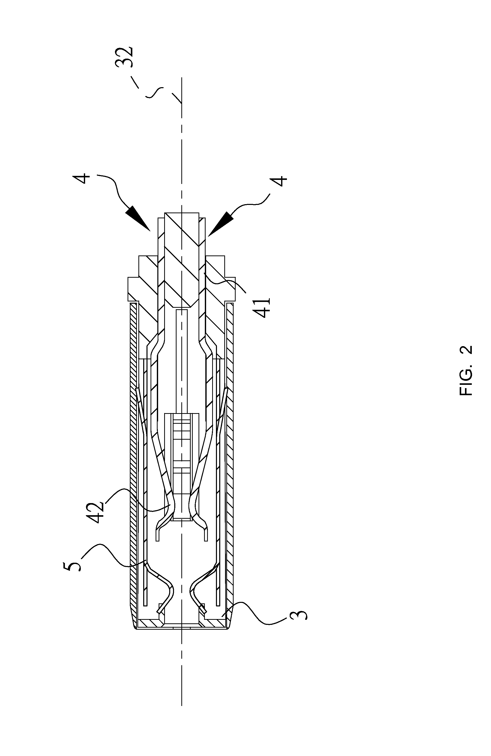
[0032]The electrical connector plug 1 includes an insulation body 3. The insulation body 3 has a base portion 31 and a mounting portion 33 fixed to the base portion 31 and extending along a longitudinal direction 32. A shielding case 2 is further mounted on the base portion 31, so that the base portion 31 can be electrically connected to the metal housing 81 of the electrical connector socket 8 by way of the shielding case 2. Upon inserting the electrical connector plug 1 into the electrical connector socket 8, the metal housings of both devices are electrically connected. Also, the electr...

fourth embodiment

[0044]A fourth embodiment according to the present invention is shown in FIGS. 14 and 15. Herein the structure of the impedance drop segment 524 is simplified and a part of the high frequency signal terminals 434 is exposed. By virtue of the impedance drop segment 524 according to the present embodiment, although it can only provide an impedance of 97 Ohms which is still better than conventional values, this approach is advantageous in material savings and still able to effectively accomplish the technical characteristics of the present invention.

[0045]Next, a fifth embodiment of the present invention is shown in FIG. 16. The skilled person in the art can easily conceive that the conductive lines in the first embodiment can be removed, the electrical connector plug 15 can be encapsulated with a plastic housing (not denoted) thus simply exposing the shielding case (not denoted), and then the resilient conductive terminals (not denoted) in the plastic housing are similarly laser welde...


PUM


Abstract

An electrical connector plug for electrical connection to an electrical connector socket. The electrical connector plug includes: an insulation body extending in a longitudinal direction and including a base portion a mounting portion fixed to the base portion; two rows of resilient conductive terminals mounted in the insulation body and arranged symmetrically in pivotal rotation with respect to the longitudinal direction, each comprising a horizontal segment fixed on the base portion and a bended protrusion contact segment extending from the horizontal segment; an electrical conductive plate mounted on the mounting portion including a front segment and an impedance drop segment, extending from the front segment toward the base portion; and a shielding case mounted on the base portion and electrically connected to the metal housing.

Description

FIELD OF THE INVENTION[0001]The present invention relates to an electrical connector plug; in particular, to an electrical connector plug applicable for Universal Serial Bus (USB) connection.BACKGROUND OF THE INVENTION[0002]In using 3C products (including Computer, Communication and Consumer electronics), it is possible to connect various external devices to the multimedia sockets equipped on 3C products in order to further expand additional or required functions. Such external devices may be, for example, an external hard disk driver, a flash drive, a multimedia audio-video apparatus or a keyboard and the like.[0003]This type of devices, e.g., a flash drive, may be configured with several convenient features supporting hot plug-in and plug-and-play operations, therefore, as a 3C product operates, it is not required to deliberately shut down electrical power to perform insert or unplug actions, catastrophic damages or burnouts in the host device or flash drive can be prevented, and ...

Claims


Application Information

Patent Timeline
IPC IPC(8): H01R24/60H01R13/6591
CPCH01R24/60H01R13/6591H01R13/6471H01R13/6474H01R13/6582H01R13/6585H01R2107/00
Inventor KAO, YA-FENTSAI, YU-LUNHOU, PIN-YUANLIAO, CHUNG-FUTSAI, WEN-HSIENCHEN, MAO-SHENG
Owner ADVANCED CONNECTEK INC
Why Eureka
Try Eureka